Self-balanced mechanical seal

A mechanical seal and self-balancing technology, applied to engine seals, mechanical equipment, engine components, etc., can solve problems such as shortening the service life of mechanical seals, wear and tear of moving rings, troublesome disassembly process, etc., to prolong service life and increase contact Surface, the effect of ensuring stability

Inactive Publication Date: 2009-09-16
NINGBO DONGLIAN MECHANICAL SEAL
View PDF0 Cites 4 Cited by
  • Summary
  • Abstract
  • Description
  • Claims
  • Application Information

AI Technical Summary

Problems solved by technology

[0003] The above three connection methods have the following disadvantages: 1. Since the effective contact area between the cylindrical arc surface of the transmission pin and the moving ring is very small, the transmission pin will not drive smoothly during the working process of the mechanical seal, and the moving ring will The stress will be relatively large, which will not only affect the dynamic sealing effect of the mechanical seal, but also shorten the service life of the mechanical seal; 2. Although the way the moving ring is tightly fitted on the rubber bellows can ensure the transmission However, the disassembly process of the moving ring is more troublesome. In other words, when the user replaces the moving ring, the rubber bellows needs to be opened to completely remove the moving ring; 3. Compared with the use of transmission pins The contact surface between the lug and the axial groove is relatively small, so the transmission of the transmission sleeve is not very smooth, and the stress on the moving ring will be relatively large. In addition, the use of transmission pins and lugs The cooperation between the ear and the groove is easy to cause the moving ring to be worn during the disassembly process, thus affecting the service life of the mechanical seal

Method used


Image

  • Self-balanced mechanical seal
  • Self-balanced mechanical seal
  • Self-balanced mechanical seal

Examples


Embodiment Construction

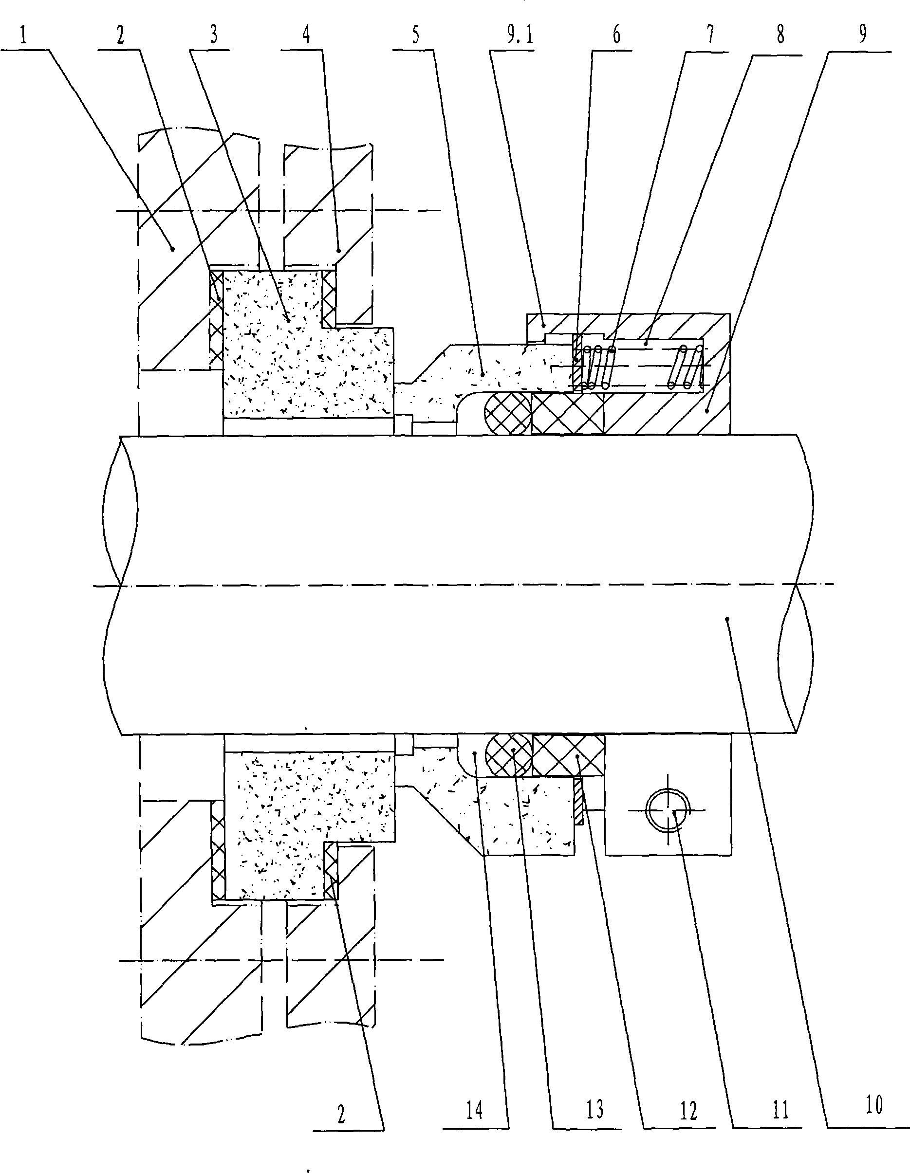
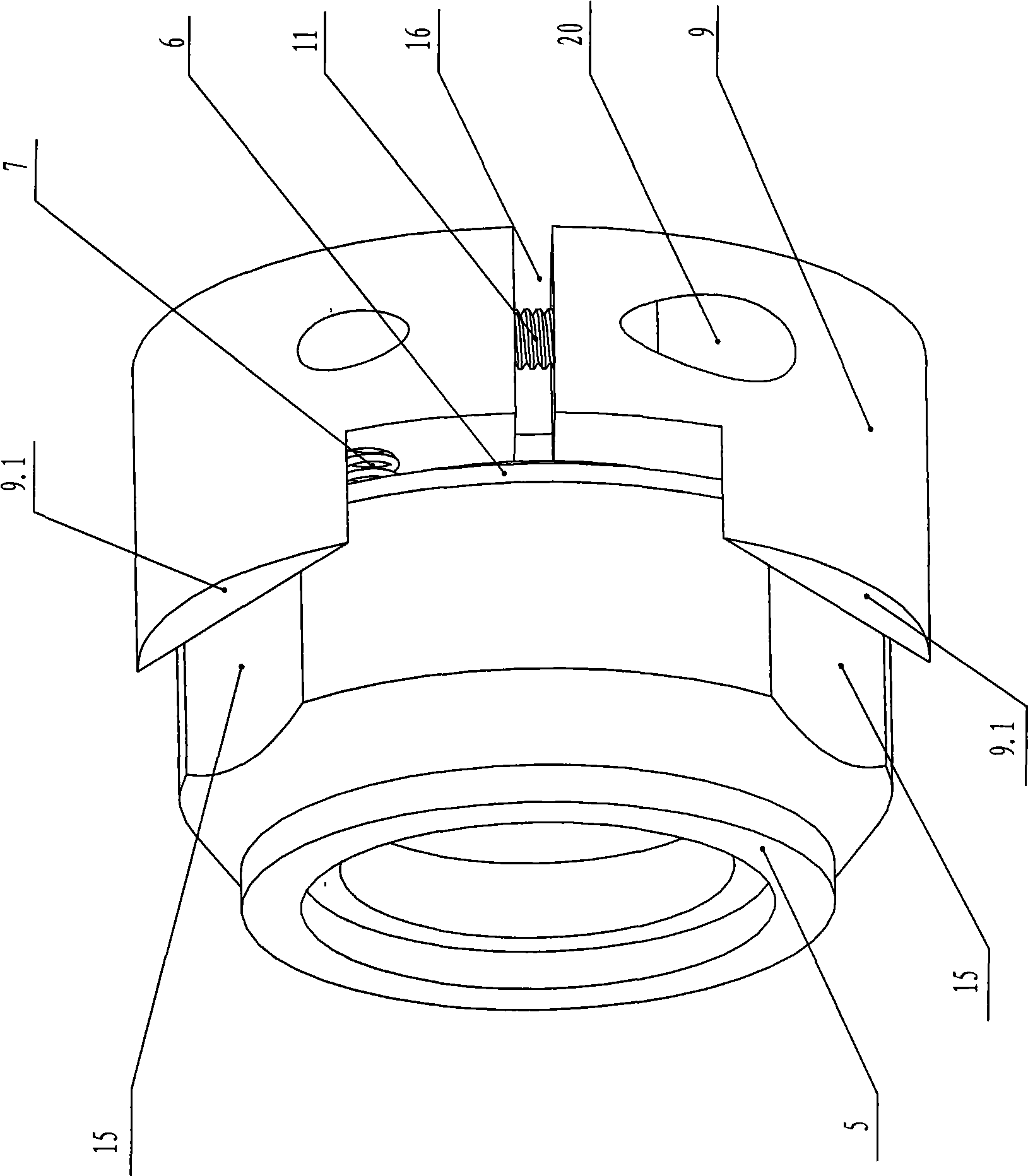
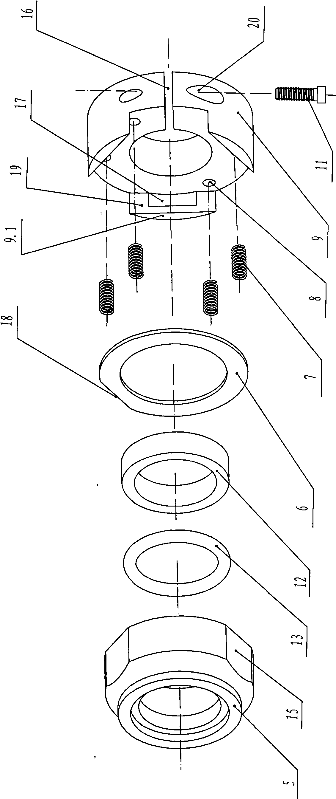
[0013] The present invention will be further described in detail below in conjunction with the drawings.

[0014] Such as figure 1 , figure 2 with image 3 As shown, in this specific embodiment, the self-balancing mechanical seal of the present invention includes a static ring assembly and a moving ring assembly; the static ring assembly specifically includes a static ring 3 and a static ring gland 4; the left end of the static ring 3 and The pump body 1 is in close contact with the steps, and the right end of the static ring 3 is in close contact with the steps of the static ring gland 4; between the left end of the static ring 3 and the pump body 1, and between the right end of the static ring 3 and the static ring gland 4 are arranged There is a static ring sealing ring 2; the moving ring assembly includes a moving ring 5, a moving sealing ring 13, a spring pad 6, four springs 7, a sealing pad 12, and a transmission seat 9 connected to the shaft 10 through a locking mechanism;...


PUM


Abstract

The invention discloses a self-balanced mechanical seal, wherein a moving ring component comprises a sealing ring (13), a spring (7), a transmission seat (9) connected with a shaft (10) and a moving ring (5); a spring groove (8) is arranged on the transmission seat (9); two ends of the spring (7) respectively abut between a spring pad (6) and the spring groove (8); three planes I (15) are uniformly distributed on circumference external surface of the moving ring (5); three convex edges (9.1) are uniformly distributed on a left end of the transmission seat (9); inner side of the convex edges (9.1) is a plane II (19) matched with the planes I (15); an arc-shaped groove (17) is arranged on the plane II (19); a straight line loss edge (18) is arranged on outer circumference of the spring seat (6); a step bore is arranged at a right end of the moving ring (5); and a moving sealing ring (13) is arranged in the step bore in an interference fit manner. The invention has long service life, stable transmission and small bearing stress for the moving ring, can make disassembling of the moving ring simple and convenient, and can prevent the moving ring from wearing in disassembling process.

Description

Technical field [0001] The invention relates to a self-balancing mechanical seal used for starting sealing in mechanical equipment such as pumps. Background technique [0002] As we all know, in order to achieve the effect of the dynamic seal, the moving ring in all mechanical seals must rotate with the shaft under working conditions. At present, the moving ring in the traditional mechanical seal generally realizes the synchronous rotation with the shaft through the following three connection methods: 1. The transmission sleeve that is interference fit with the shaft is connected with a transmission pin, and the moving ring is provided with a transmission pin hole; One end of the drive pin is located in the drive pin hole. After adopting this structure, the drive sleeve that is in interference fit with the shaft can drive the moving ring to rotate through the drive pin; 2. The non-working end of the moving ring is tightly fitted to the rubber bellows head The end of the rubber be...

Claims


Application Information

Patent Timeline
Patent Type & Authority Applications(China)
IPC IPC(8): F16J15/16F16J15/24
Inventor 李友宝励才勋励永平
Owner NINGBO DONGLIAN MECHANICAL SEAL
Why Eureka
Try Eureka