Tubular flexible neon lamp

A neon light and flexible technology, which is applied to the damage prevention measures of lighting devices, lighting and heating equipment, semiconductor devices of light-emitting elements, etc. It can solve the problems of point light sources, products that cannot be cut, and light-emitting angles that cannot be reached. Cost-saving, uniform scattering, and the effect of eliminating the need for fixed brackets

Inactive Publication Date: 2009-09-16
姚志峰
View PDF1 Cites 7 Cited by
  • Summary
  • Abstract
  • Description
  • Claims
  • Application Information

AI Technical Summary

Problems solved by technology

[0004] 1. It does not produce a uniform luminous effect around the product, because the plastic mixed light protective layer and light mixed light guide layer in this invention are all transparent materials, so it is obvious that the product will have the disadvantage of point light sources during use ;
[0005] 2. Since the LEDs in the three channels are not in the same cross-section in this invention, there is a shortcoming that the product cannot be cut, because the distance between the LEDs of the product is too close, and the parallel connection points of the LEDs and the control lines in the three channels cannot be in the same cross section. At the same position, if the spacing is increased, the disadvantage of point light sources will be more obvious;
[0006] 3. Since the LEDs used in this invention are ordinary columnar LEDs, and the installation method is to lie on the side in the LED channel, and the concentrated point of light emitted by this type of LED is on the top of the LED, the light in this invention It is not fully utilized, and the light-emitting angle of its LEDs is between 30° and 45°, so the light-emitting angles of the LEDs in the three channels cannot reach a light-emitting angle of 360° in the lateral direction;

Method used


Image

  • Tubular flexible neon lamp
  • Tubular flexible neon lamp
  • Tubular flexible neon lamp

Examples


Embodiment Construction

[0035] The present invention will be further described below in conjunction with the accompanying drawings and specific embodiments.

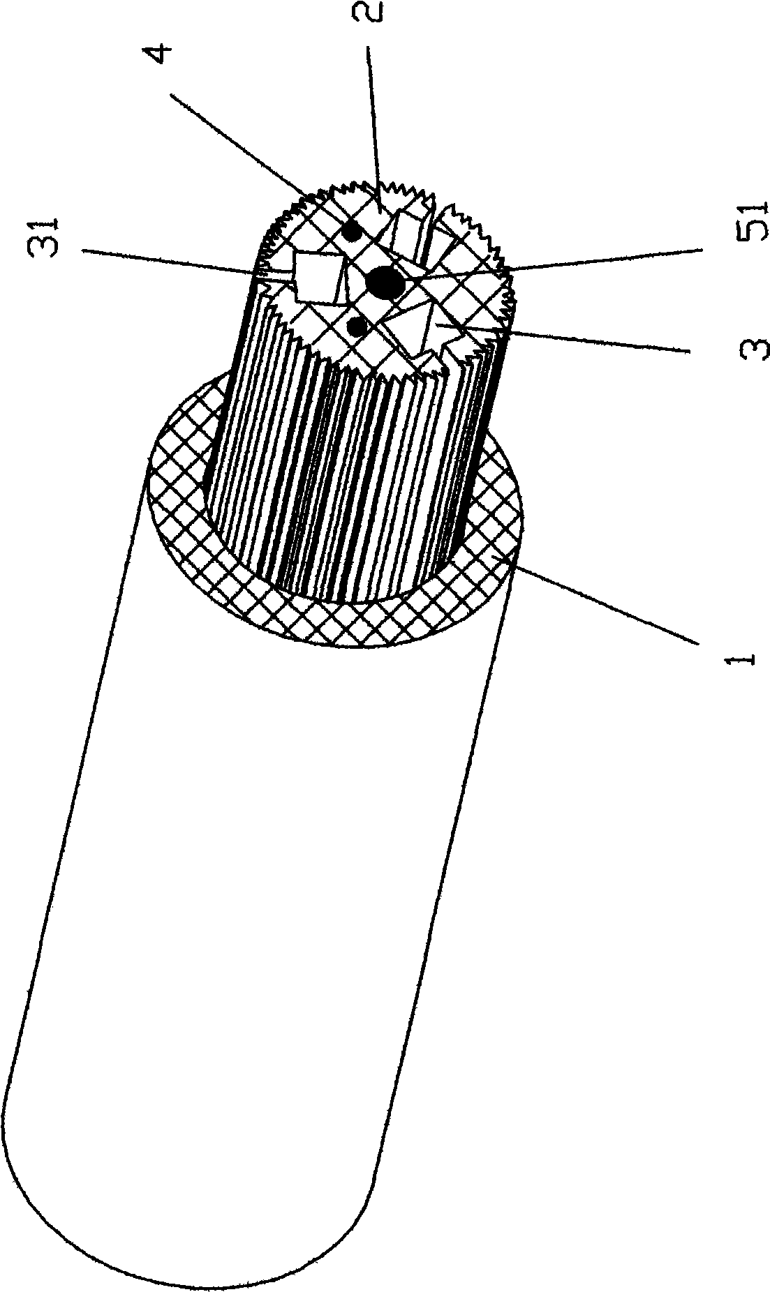
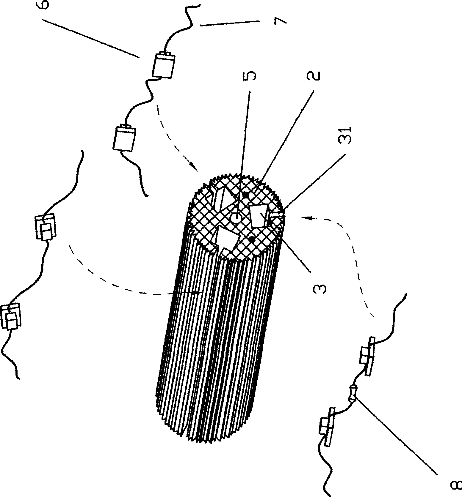
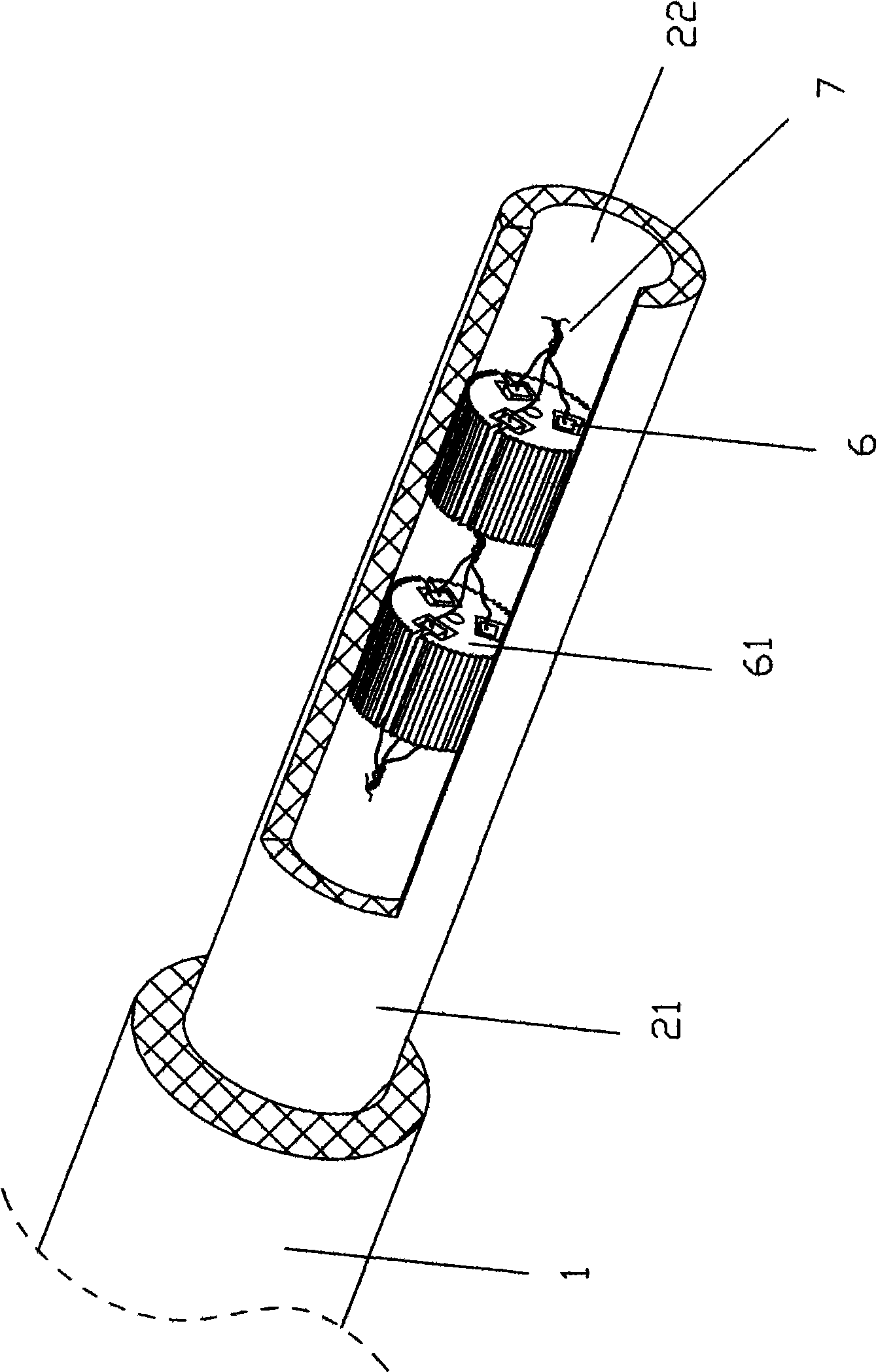
[0036] refer to Figure 1-2 . The present invention includes a flexible lamp body core wire 2, the flexible lamp body core wire is extruded and formed by flexible plastic, the lamp body core wire is a light-transmitting plastic strip, and its cross-sectional profile is circular or triangular, or it can be For other shapes, the material is transparent plastic material, or it can be milky white or colored plastic with light transmission but opaque. In order to produce better light scattering effect, several horizontal or vertical rib stripes can be set on the surface of the core wire. The core wire is provided with at least two wires 4 which can be electrically connected to the power supply along the longitudinal direction, and a number of slots 3 are arranged in the core wire along the longitudinal direction. There is at least a cut 31 between t...


PUM


Abstract

The invention discloses a tubular flexible neon lamp comprising a flexible lamp body core wire. At least two leads which can be electrically connected with a power supply are arranged in the core wire along the longitudinal direction; a plurality of groove holes are arranged in the core wire along the longitudinal direction; at least one notch is arranged between the inner wall and the outer wall of the groove hole; a plurality of groups of light source groups and electronic elements are arranged in the groove holes; the light of each luminous body in the same light source group has different directions of illumination and the luminous face of each light source group faces the outer surface of the flexible lamp body core wire and forms luminous angle of 360 degrees wholly in the horizontal direction; and the periphery of the flexible lamp body core wire is coated with a plastic light diffusion layer which is euphotic but opaque. Therefore, the tubular flexible neon lamp has the advantages of uniform light emitting, high light utilization ratio, high brightness and low cost and can emit light all over the body.

Description

Technical field [0001] The invention relates to a lighting device, in particular to a tubular flexible neon lamp. Background technique [0002] Because neon lights have the advantages of continuous, uniform, and high luminous brightness, they are widely used as advertisements or decorations. However, neon lights use glass tubes, so they are subject to great restrictions during packaging and transportation, and are easily broken during transportation. Professionals must use professional tools to operate during installation or maintenance, so there is a lot of inconvenience. [0003] For this reason, an inventor invented a patent application number: 200520103027.X named "Tubular Uniform Light LED Flexible Light Strip". The purpose of luminous uniformity. And find that this invention has following shortcoming in practical application: [0004] 1. It does not produce a uniform luminous effect around the product, because the plastic mixed light protective layer and light mixed...

Claims


Application Information

Patent Timeline
Patent Type & Authority Applications(China)
IPC IPC(8): F21S4/00F21V23/00F21V19/00F21V15/02F21Y101/02F21S4/26F21Y103/10F21Y115/10
Inventor 姚志峰
Owner 姚志峰
Why Eureka
Try Eureka