Vibration Generating Device

A technology of vibration generating device and transmission device, which is applied in the direction of fluid using vibration, transportation and packaging, chemical/physical process, etc., which can solve the problems of uneven vibration, increase cleaning, and affect the effect of vibration, so as to avoid vibration Effect of uneven or unidirectional vibration

Inactive Publication Date: 2014-07-09
WISTRON CORP
View PDF6 Cites 20 Cited by
  • Summary
  • Abstract
  • Description
  • Claims
  • Application Information

AI Technical Summary

Problems solved by technology

However, the placement of the vibration motor will affect the vibration effect. For example, the vibration effect is poorer in places far away from the vibration motor, thus causing the problem of uneven vibration
[0003] In addition, another method uses a straw to repeatedly suck and release the test sample, so that the particles in the test sample are dispersed in the test tube, which can also achieve the effect of stirring, but this contact stirring method is prone to contamination of the straw and increased cleaning / disinfection costs And other problems, it is not suitable for a large number of detection projects, and needs to be further improved

Method used


Image

  • Vibration Generating Device
  • Vibration Generating Device
  • Vibration Generating Device

Examples


no. 1 example

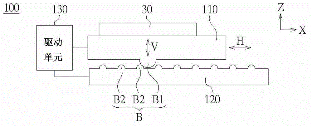
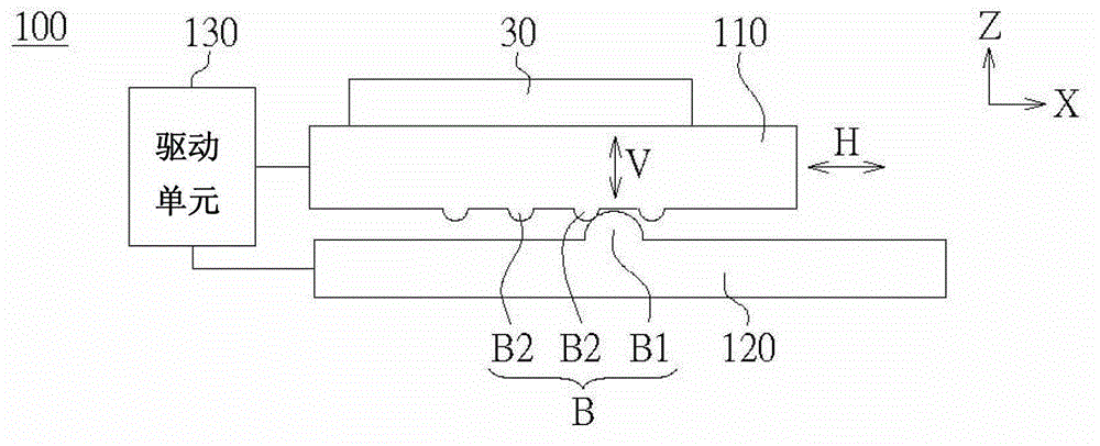
[0046] Please refer to Figure 2A and 2B , respectively depicting a schematic view of the vibration generating device 100 according to an embodiment of the present invention. The vibration generating device 100 includes a working platform 110 , a counter platform 120 and a driving unit 130 . The working platform 110 is used for carrying a workpiece 30 , and the workpiece 30 is disposed on one side of the working platform 110 . The opposite platform 120 is adjacent to the other side of the working platform 110 . The working platform 110 and the opposite platform 120 are in contact with each other with at least two bumps B1 and B2 projecting oppositely between the working platform 110 and the opposite platform 120 .

[0047] For example, in Figure 2A Among them, the working platform 110 is disposed above the opposite platform 120 and fixed by clamps (not shown), so as to keep the working platform 110 to move horizontally on the opposite platform 120 smoothly. At least one ...

no. 2 example

[0054] Please refer to Figure 5 , which is a schematic diagram of a vibration generating device 200 according to an embodiment of the present invention. The vibration generating device 200 includes a working platform 210 , a counter platform 220 and a driving unit 230 . Regarding the working platform 210, the relative platform 220, and a plurality of projections (not shown) that are arranged between the working platform 210 and the relative platform 220 and contact each other, the arrangement thereof is similar to that of the first embodiment, please refer to Figure 2A-2B , 3A-3C and 4A-4C and their descriptions will not be repeated here.

[0055] The difference between this embodiment and the first embodiment is that the driving unit 230 is coupled to the working platform 210 and the relative platform 220 to drive the working platform 210 and the relative platform 220 to move relative to each other on a two-dimensional plane. For example, see Figure 6C The vibration gen...

no. 3 example

[0058] Furthermore, please refer to Figure 6D and 6E In the second embodiment, the drive unit is in addition to Figure 6A In addition to the linear transmission device 142 to drive the working platform 110 or the relative platform 120, a non-linear transmission device (such as a suspension transmission device or a ground-shaking transmission device) can also be used to drive the working platform 110 or the relative platform 120, so as to Make the working platform 110 or the relative platform 120 generate a horizontal movement.

[0059] For example, see Figure 6D The vibration generating device 104, the drive unit 134 includes a controller 141 and a suspension transmission 145, the suspension transmission 145 is used to support the work platform 110, so that the work platform 110 can be placed on the opposite platform 120 smoothly, And drive the working platform 110, so that the working platform 110 has a horizontal movement relative to the relative platform 120. The hori...


PUM


Abstract

A vibration generating device including a working platform, an opposite platform and a driving unit is provided. The working platform carries a workpiece disposed on one side of the working platform. The opposite platform is adjacent to another side of the working platform. The working platform and the opposite platform contact to each other via at least two bumps reversely protruded between the working platform and the opposite platform. The driving unit is coupled to the working platform or the opposite platform to drive the working platform or the opposite platform to move in a horizontal direction, and the working platform generates a vibration in a vertical direction.

Description

technical field [0001] The present invention relates to a vibration generating device, and in particular to a vibration generating device with horizontal movement and vertical vibration. Background technique [0002] Conventional vibration generating devices are nothing more than using vibration motors to transmit vibration energy to a workpiece. For example: place a test tube containing a test sample on a vibrating plate, and run the vibrating motor at high speed to make the vibrating plate vibrate. The particles in the test sample are dispersed in the test tube after being vibrated, so as to achieve the effect of stirring. However, the placement of the vibration motor will affect the vibration effect. For example, the vibration effect is poorer in places far away from the vibration motor, thus causing the problem of uneven vibration. [0003] In addition, another method uses a straw to repeatedly suck and release the test sample, so that the particles in the test sample ...

Claims


Application Information

Patent Timeline
Patent Type & Authority Applications(China)
IPC IPC(8): B06B1/12
CPCB06B1/00B01F11/02B06B1/10
Inventor 江奇展林志冠
Owner WISTRON CORP
Why Eureka
Try Eureka