Deviation correction method for measurement of rail wear based on laser vision

A rail wear and laser technology, applied in the direction of measuring devices, optical devices, instruments, etc., can solve the problems of reducing the accuracy of rail wear measurement, it is difficult to ensure verticality, etc., to improve utilization, improve accuracy, and eliminate rail wear measurement effect of error

Inactive Publication Date: 2009-09-16
BEIHANG UNIV
View PDF3 Cites 32 Cited by
  • Summary
  • Abstract
  • Description
  • Claims
  • Application Information

AI Technical Summary

Problems solved by technology

However, during the installation process of the laser vision sensor, it is difficult to ensure that the light plane projected by it is perpendicular to the longitudinal axis of the rail
In addition, the laser vision sensor is installed at the bottom of the train. When the train is running, the light plane projected by the laser vision sensor is not perpendicular to the longitudinal axis of the rail due to the vibration of the train, thereby reducing the accuracy of rail wear measurement.

Method used


Image

  • Deviation correction method for measurement of rail wear based on laser vision
  • Deviation correction method for measurement of rail wear based on laser vision
  • Deviation correction method for measurement of rail wear based on laser vision

Examples


Embodiment Construction

[0031] The technical solutions of the present invention will be further elaborated below in conjunction with the accompanying drawings and specific embodiments.

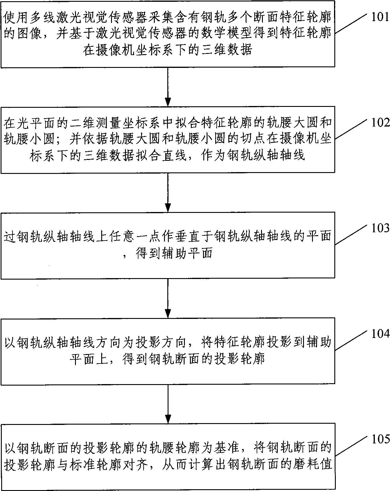
[0032] A deviation correction method for laser vision rail wear measurement provided by the present invention, such as figure 1 As shown, it mainly includes the following steps:

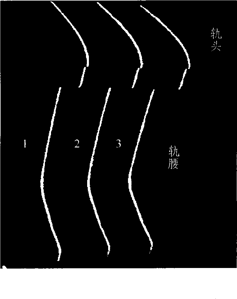
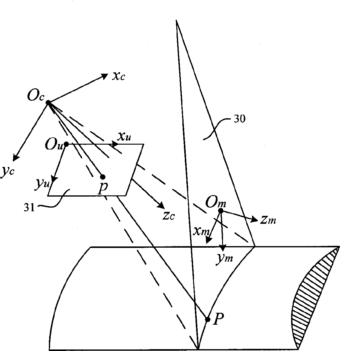
[0033] In step 101, the multi-line laser vision sensor is used to collect images containing feature contours of multiple cross-sections of the rail, and the three-dimensional data of the feature contours in the camera coordinate system is obtained based on the mathematical model of the laser vision sensor.

[0034] In the present invention, a multi-line laser vision sensor is used to measure multiple sections of the inner rail waist and rail head of the rail. The multi-line laser vision sensor contains two or more than two light plane projectors, which can project a plurality of parallel light plane. Preferably, a laser vision sensor capa...


PUM


Abstract

The invention discloses a deviation correction method for measurement of rail wear based on laser vision, comprising the steps of dividing a rail waist profile of a characteristic profile of dividing a cross section of a rail obtained by the measurement by a laser vision sensor into a rail waist big circle and a rail waist small circle; fitting a rail longitudinal shaft line according to a tangent point of the rail waist big circle and the rail waist small circle; projecting the characteristic profile to an auxiliary plane which is vertical to the rail longitudinal shaft line to obtain a projection profile of the cross section of the rail; and calculating the wear value of the cross section of the rail by aligning a standard profile of the cross section of the rail with the projection profile. The measurement error of the rail wear caused by that a light plane projected by the laser vision sensor is not vertical to the rail longitudinal shaft line can be eliminated based on the method.

Description

technical field [0001] The invention relates to laser vision measurement technology, in particular to a deviation correction method for laser vision rail wear measurement. Background technique [0002] Regular inspection of rails is very important for reasonable planning and low-cost maintenance of railway transportation: on the one hand, in the early stages of rail wear and deformation, rail inspection helps to formulate a reasonable railway maintenance schedule to avoid dangerous situations; On the other hand, effective track inspection will lay the foundation for the transformation of track from periodic maintenance to condition-based maintenance, so that limited manpower and equipment resources can be better utilized, and track maintenance costs can be effectively saved. [0003] At present, many research institutions and scholars at home and abroad have studied the detection methods of rail wear, and successfully developed various measuring devices. According to differe...

Claims


Application Information

Patent Timeline
Patent Type & Authority Applications(China)
IPC IPC(8): G01B11/24G01B11/03G01B11/02
Inventor 张广军孙军华刘震魏振忠王伟华李庆波
Owner BEIHANG UNIV
Why Eureka
Try Eureka