
Method of executing fire alarm by distributed optical fiber temperature sensor

A technology of temperature sensor and distributed optical fiber, which is applied in fire alarms with electrical effects and thermometers that give average/integral values, etc., can solve the problem of increasing uncertainty of temperature values, reducing the effectiveness of differential temperature alarms, and erroneous report and other issues to achieve the effect of improving stability

Active Publication Date: 2009-09-16
浙江振东光电科技有限公司
View PDF0 Cites 18 Cited by
  • Summary
  • Abstract
  • Description
  • Claims
  • Application Information

AI Technical Summary

Problems solved by technology

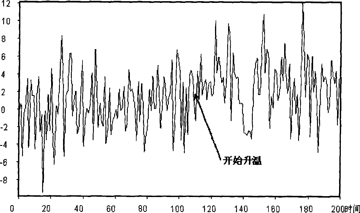
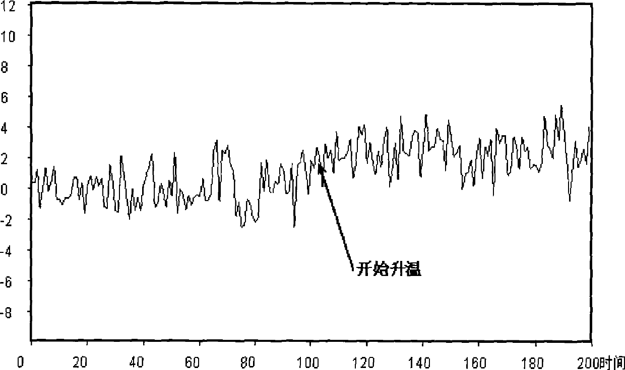
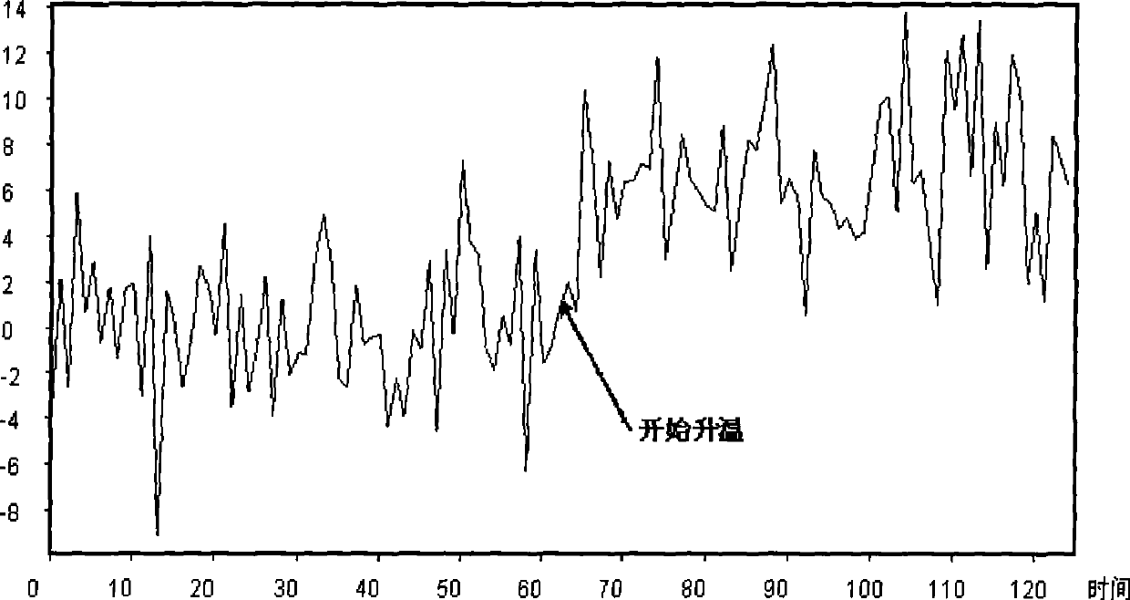
[0006] However, due to the existence of noise data in the temperature data collected by the distributed optical fiber temperature sensor system (DTS), the uncertainty of the temperature values ​​monitored twice before and after a certain measurement point in the time-space domain increases, which makes The differential temperature alarm value cannot be set too low, otherwise it will cause false alarms, thereby reducing the effectiveness of the differential temperature alarm

Method used


Image

  • Method of executing fire alarm by distributed optical fiber temperature sensor
  • Method of executing fire alarm by distributed optical fiber temperature sensor
  • Method of executing fire alarm by distributed optical fiber temperature sensor

Examples


Embodiment Construction

[0026] The present invention will be further described in detail below with reference to the embodiments of the accompanying drawings.

[0027] In the present embodiment, the method of using a distributed optical fiber temperature sensor system for fire alarm includes the following steps:

[0028] Step 1: Set the differential temperature alarm value T f =10°C;

[0029] Step 2: Intercept 16 groups of connected temperature record data collected by the distributed optical fiber temperature sensor system, and denote it as T in chronological order 1 [1, 2, 3, ... m], T 1 [1, 2, 3, ... m] ... T 16 [1, 2, 3,…m], where m is the total number of actual temperature measurements in the spatiotemporal domain of the optical fiber by the distributed optical fiber temperature sensor system, T a [b] represents the measured temperature at the bth place in the temperature record data of the ath group, 1≤a≤n, 1≤b≤m;

[0030] Step 3: Set the calculation point p=100, and the value range of p i...


PUM


Abstract

The invention relates to a method of executing fire alarm by distributed optical fiber temperature sensor system; the method is characterized by comprising the steps of: step one, setting differential temperature alarm value Tf; step two, intercepting the n groups of conterminal temperature recording data collected by the distributed optical fiber temperature sensor system; step three, calculating the average measuring temperature ***...*** of the first to ith group of the temperature recording data T1 <1, 2, 3,...M> at pth; step four, calculating the historic measuring temperature mean value *** at pth; step five, subtracting the historic measuring temperature mean value *** at pth by the average measuring temperature *** at pth in n group of temperature recording data Tn <1, 2, 3,...M>; step six, comparing the temperature difference Tp at pth with the differential temperature alarm value Tf, alarming when the temperature difference Tp at pth is more than the differential temperature alarm value Tf, or else not. Compared with the prior art, the invention has the advantages of effectively reducing the effect of the noise to the differential temperature valve and improving the stability of the differential temperature value.

Description

technical field [0001] The invention relates to a method for alarming fire by adopting a distributed optical fiber temperature sensor system. Background technique [0002] In projects such as highway tunnels and high-voltage cables, fire monitoring has always been the focus of the transportation and electric power departments. If there is no effective fire monitoring, when a fire occurs, serious accidents often occur, which will bring harm to the life and property of the country and the people. In recent years, tunnels have become longer and longer, and more and more urban high-voltage cables are buried underground, making the importance of fire monitoring more and more prominent. When the fire just broke out, the fire intensity, temperature and destructiveness are relatively small. If the fire can be found and extinguished at this stage, the destructiveness and loss of the fire can be greatly reduced. [0003] Distributed optical fiber temperature sensor system (DTS) is ba...

Claims


Application Information

Patent Timeline
Patent Type & Authority Applications(China)
IPC IPC(8): G08B17/06G01K3/02
Inventor 鲁展夏旭鹏杨如祥
Owner 浙江振东光电科技有限公司
Learn More