Control device and control method for cooling frames of hot milling roll

A technology of cooling control and cooling device, which is applied in the direction of temperature control without auxiliary power supply, temperature control, temperature control using electric mode, etc. It can solve the problems of increasing the frequency of cooling water volume increase and decrease, complex control structure, and reduced temperature accuracy.

Active Publication Date: 2009-09-23
HITACHI LTD
View PDF4 Cites 29 Cited by
  • Summary
  • Abstract
  • Description
  • Claims
  • Application Information

AI Technical Summary

Problems solved by technology

Therefore, when the control technology of Patent Document 3 is applied to micro tandem hot rolling, not only the control structure becomes unnecessarily complicated, but also the operation of changing the amount of cooling water for each stage corresponds to the FDT of the steel plate. The temperature changes may overlap, these situations may become the interference of the winding temperature control in the subsequent process, and also increase the frequency of the increase or decrease of the amount of cooling water
[0015] The control technology of Patent Document 4 performs water injection control based on the result of calculating the temperature change in the finish rolling process of the steel plate based on a preset temperature model or actual parameters. Therefore, the temperature accuracy may vary depending on the actual FET or steel plate speed. decrease due to changes in

Method used


Image

  • Control device and control method for cooling frames of hot milling roll
  • Control device and control method for cooling frames of hot milling roll
  • Control device and control method for cooling frames of hot milling roll

Examples


Embodiment Construction

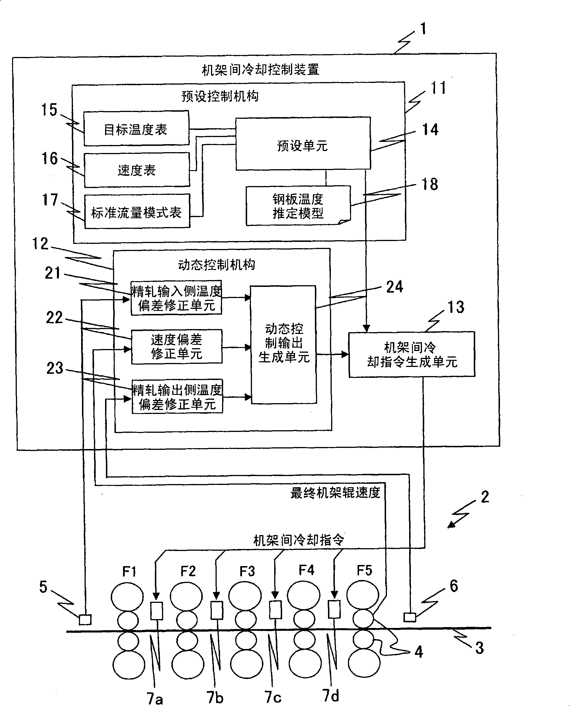
[0071] Next, modes for implementing the present invention will be described. figure 1 It is a figure which shows the structure of the inter-stand cooling control apparatus 1 of 1st Embodiment in connection with the finish rolling mill 2 of a control object. The inter-stand cooling control device 1 receives various signals from the finish rolling mill 2 and outputs control signals to the finish rolling mill 2 . In addition, "... mechanism or unit" described in the following description may also be referred to as "... department".

[0072] The finishing mill 2 includes five stands F1 to F5 (hereinafter, "stand" is omitted as appropriate, and only described with symbols). The steel plate 3 conveyed to the finish rolling mill 2 from a rough rolling mill not shown in the drawing is moved from left to right while being rolled by respective rolls 4 of stands F1 to F5 . In addition, the finish rolling mill 2 is provided with a finish-rolling entry-side thermometer 5, which is a fini...


PUM

PropertyMeasurementUnit
thicknessaaaaaaaaaa

Abstract

The present invention provides a control device for cooling between frames, by means of controlling a cooling device for cooling frames of a finishing mill through filling cooling water, it is capable of controlling with a higher precision the steel plate temperature of an output side of the finishing mill and further reducing a fluctuation frequentness of the cooling water amount. The cooling device (1) includes a presetting control mechanism (11), for controlling the cooling water amount of cooling devices (7a-7d) of the finishing mill (2) in a mode that the FDT (finishing delivery side temperature) of the steel plate (3) is consistent with an anticipant target temperature, before the steel plate is cooled by the cooling water, the FDT is estimated by a steel plate temperature estimation model (18), then the cooling water amount of the cooling device is calculated based on the FDT and a presetting control output is generated; a dynamic control mechanism (12), obtaining a state quantity of the rolling steel plate, calculating a altering amount of the cooling water amount based on the state quantity and generating a dynamic control output; and a frame cooling instruction generation unit (13), generating and outputting frame cooling instructions based on the presetting control output and the dynamic control output.

Description

technical field [0001] The present invention relates to control of inter-stand cooling by injecting water between the stands in order to adjust the temperature of a steel plate on the output side of a finishing mill during hot rolling to a predetermined target temperature. Background technique [0002] In the hot rolling, the finish rolling for adjusting the shape or size of the steel sheet is performed by a finish rolling mill equipped with a plurality of stands. Then, cooling is performed in the finish rolling mill to adjust the finish rolling exit side temperature (steel plate temperature on the finish rolling mill exit side, hereinafter referred to as FDT) to a predetermined target temperature. This cooling is generally achieved by injecting cooling water into the steel plate being rolled in a spray state by an inter-stand cooling device installed between each stand on the finish rolling mill. In this cooling, the FDT is controlled according to the relationship between ...

Claims


Application Information

Patent Timeline
Patent Type & Authority Applications(China)
IPC IPC(8): B21B37/76G05D23/19G05D23/01
Inventor 鹿山昌宏栗林健
Owner HITACHI LTD
Why Eureka
Try Eureka