Double-path high-precision temperature demodulation method based on distributed optical fiber Raman sensing system

A distributed optical fiber and Raman sensing technology, which is applied in the field of temperature demodulation, can solve the problems of low temperature measurement accuracy and achieve the effects of excellent temperature measurement accuracy, optimized temperature accuracy, and reasonable design

Active Publication Date: 2020-04-14
TAIYUAN UNIV OF TECH
View PDF4 Cites 7 Cited by
  • Summary
  • Abstract
  • Description
  • Claims
  • Application Information

AI Technical Summary

Problems solved by technology

[0005] In order to solve the problem that the existing distributed optical fiber Raman sensing system has low temperature measurement accuracy and its technical bottleneck of being unable to change 1°C causes its application to be limited, the present invention proposes a distributed optical fiber Raman sensing system based on The dual-path high-precision temperature demodulation method, by introducing the fiber temperature sensitivity factor, recalibrates the Raman scattering signal intensity in the sensing fiber to improve the temperature sensitivity of its spontaneous Raman scattering to optimize the temperature accuracy of the system

Method used


Image

  • Double-path high-precision temperature demodulation method based on distributed optical fiber Raman sensing system
  • Double-path high-precision temperature demodulation method based on distributed optical fiber Raman sensing system
  • Double-path high-precision temperature demodulation method based on distributed optical fiber Raman sensing system

Examples


Embodiment Construction

[0025] In order to make the purpose, technical solutions and advantages of the embodiments of the present invention clearer, the technical solutions in the embodiments of the present invention will be clearly and completely described below. Obviously, the described embodiments are part of the embodiments of the present invention, rather than All the embodiments; based on the embodiments of the present invention, all other embodiments obtained by persons of ordinary skill in the art without creative work all belong to the protection scope of the present invention.

[0026] An embodiment of the present invention provides a dual-path high-precision temperature demodulation method based on a distributed optical fiber Raman sensing system, including the following steps:

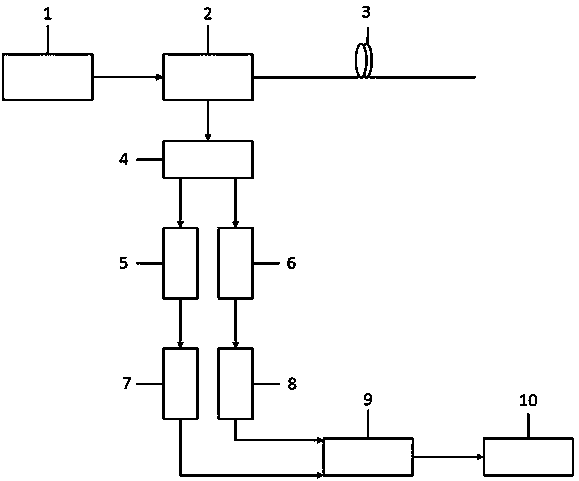
[0027] S1. Build a measuring device, so that the output light of the pulsed laser 1 is output to the sensing fiber 3 through the first port and the second port of the circulator 2, and the signal acquisition device...


PUM

PropertyMeasurementUnit
lengthaaaaaaaaaa
wavelengthaaaaaaaaaa

Abstract

The invention belongs to the field of temperature demodulation in a distributed optical fiber sensing system, and discloses a double-path high-precision temperature demodulation method based on a distributed optical fiber Raman sensing system. The method comprises the following steps: S1, carrying out device connection; S2, a calibration and measurement stage: respectively collecting light intensity ratios of anti-Stokes light and Stokes light of each point in a reference optical fiber ring and any position L of a sensing optical fiber; S3, a calibration measurement stage: respectively collecting light intensity ratios of backward anti-Stokes light and Stokes light of the sensing optical fiber when a calibration optical fiber ring is located at different positions, and carrying out calculation and linear fitting to obtain all function values of a temperature sensitive factor of the sensing optical fiber along with the distance; S4, a measurement stage: collecting the light intensity ratio of the anti-Stokes light and the Stokes light of each point in the reference optical fiber ring and each position in the sensing optical fiber; and S6, calculating to obtain all temperature information along the sensing optical fiber. According to the invention, the problem of low temperature measurement precision in the prior art is effectively solved, and the method can be widely applied tothe distributed optical fiber sensing system.

Description

technical field [0001] The invention belongs to the field of temperature demodulation in a distributed optical fiber sensing system, in particular to a high-precision Raman temperature demodulation method based on Stokes light demodulation anti-Stokes light. Background technique [0002] The distributed optical fiber Raman temperature measurement system has the advantages of anti-electromagnetic interference, anti-corrosion, electrical insulation, high sensitivity, good reliability, long service life, low cost, and good compatibility with ordinary optical fibers. Its temperature measurement principle is based on optical fiber Spontaneous Raman scattering and optical time-domain reflectometry localization techniques. The system injects high-power, narrow-pulse-width pulsed light waves into the multi-mode sensing fiber, and records the reflected back-spontaneous Raman backscattering light intensity at the same time, and then demodulates the temperature of each position along t...

Claims


Application Information

Patent Timeline
Patent Type & Authority Applications(China)
IPC IPC(8): G01K11/32G01K11/324
CPCG01K11/32G01K11/324
Inventor 张明江李健吴强周新新张建忠闫宝强许扬余涛于福浩
Owner TAIYUAN UNIV OF TECH
Why Eureka
Try Eureka