

Vapor-liquid separation method of evaporator and evaporator
A vapor-liquid separation and evaporator technology, applied in evaporator/condenser, heat exchanger shell, indirect heat exchanger, etc., can solve the problems of low heat exchange efficiency, insufficient suction force, uneven heat exchange, etc. Achieve the effect of improving heat transfer performance, ensuring steam resistance, and ingenious structural design
Inactive Publication Date: 2011-01-05
TSINGHUA UNIV
View PDF2 Cites 0 Cited by
- Summary
- Abstract
- Description
- Claims
- Application Information
AI Technical Summary
Problems solved by technology
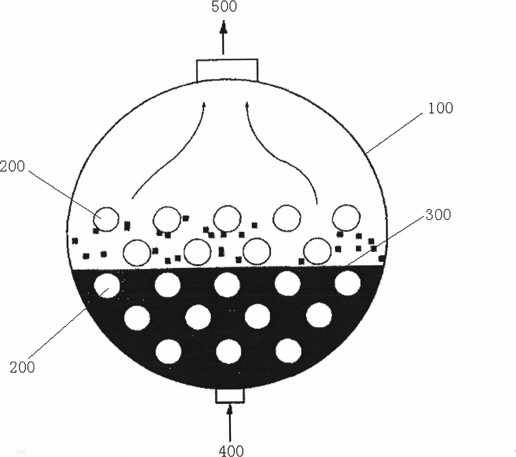
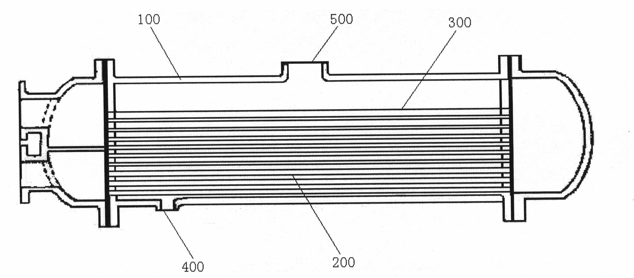
The traditional flooded evaporator has the following problems: 1. Due to the large amount of refrigerant 300 in the shell 100 and the deep liquid level, the heat transfer is uneven and the heat transfer coefficient is low during the heat transfer process, resulting in Low thermal efficiency
2. It is difficult to ensure that the boiling refrigerant 300 working medium gas is a dry gas when it exits the outlet 500, so there may be liquid entering the compressor for compression, thereby damaging the compressor
3. The volume of the equipment is large
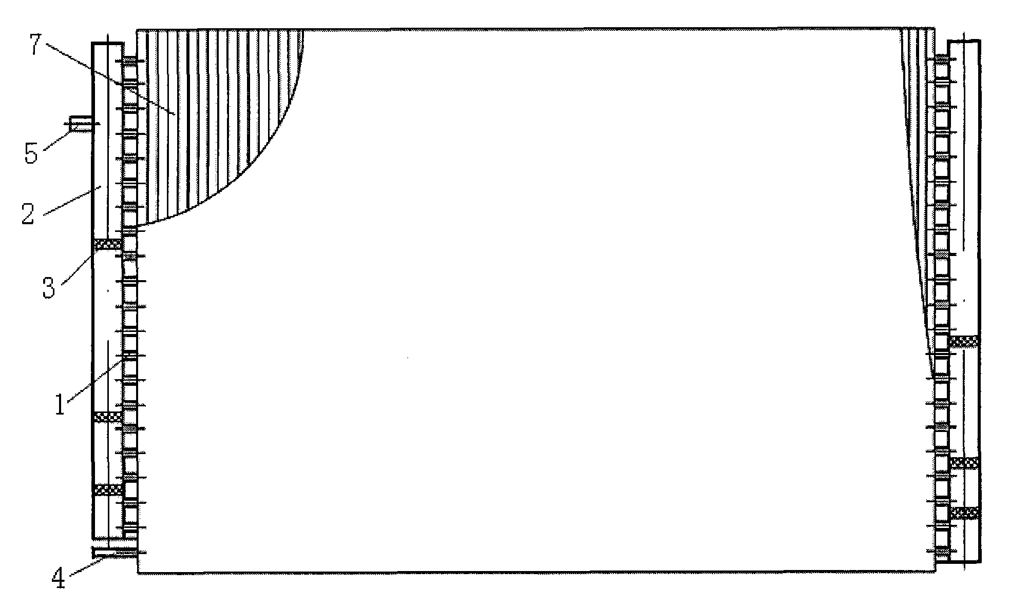
The header 102 in the above two patents both use a single drain pipe 202 as a leaking liquid vapor blocking device. This thinner drain pipe 202 can better prevent the separated gas from the header 102 from flowing out of the drain pipe. 202 leaks, but this structure brings the following problems: First, the diameter of the drain pipe 202 is smaller than that of the header 102, the flow range of the condensate is greatly restricted, and sometimes there is a problem of poor drainage
Although a liquid dispensing device (as shown in FIG. 6 ) consisting of a solid top cover 302, a porous core body 402 and a discharge pipe wall 502 is adopted in the latter patent, since the upper surface of the liquid dispensing device adopts a solid top cover 302 , the contact surface between the condensate and the liquid separator during the operation of the condenser is the side surface of the porous medium, so the liquid separation driving force of the liquid separator is mainly the capillary suction force of the porous core 402, and the size of the suction force is determined by the selected The structural parameters of the porous medium are determined, and the self-adjusting ability is weak. When the amount of condensate is large, there may be a problem of insufficient suction, which affects the effect of liquid separation; in addition, the structure of the liquid separation device is relatively complicated. In industrial production Large-scale production and subsequent installation work will bring certain difficulties
Method used
View moreImage
Smart ImageViewing Examples

Examples
Embodiment 1
Embodiment 2
Embodiment 3
Login to View More PUM
 Abstract
The invention relates to a vapor-liquid separation method of an evaporator and the evaporator, which comprises the following details: (1) both ends of at least a group of heat exchange tubes are respectively provided with a header; the two headers are provided with a plurality of leakage vapor resistance devices in an alternation way which can be embedded in the headers; the two headers are divided into a plurality of liquid separation spaces which are sequentially communicated; the leakage vapor resistance devices are provided with at least one valent weight main hole and a plurality of valent weight pilot holes; (2) when dropsy in the liquid separation spaces has few, a liquid membrane formed by the main hole and the pilot holes can prevent gas from entering into the liquid separation space of the next level header; (3) when dropsy in the liquid separation spaces has more, the dropsy firstly perforates the main hole and outflows; while the pilot holes is continously sealed by the liquid membrane formed by the top; (4) when the thickness of the dropsy layer in the liquid separation spaces enlarges, the dropsy gradually perforates the pilot holes and simultaneously outflows from the main hole and the pilot holes. The evaporator is the evaporator adopting the vapor-liquid separation method and the leakage vapor resistance devices and effectively solves the problem that the drainage amount in the evaporator of the prior art is limited.
Description
Vapor-liquid separation method of evaporator and evaporator technical field The invention relates to an evaporator, in particular to a vapor-liquid separation method of the evaporator and the evaporator. Background technique The traditional flooded evaporator generally adopts a horizontal type, consisting of a shell 100 and a heat exchange tube 200, and the heat exchange tube 200 is arranged to be immersed in the refrigerant 300 liquid in the evaporator (as shown in Figure 1 and Figure 2 ). The refrigerant 300 enters the housing 100 from the inlet 400 at the bottom of the housing 100, is heated outside the heat exchange tube 200 by the heating medium in the heat exchange tube 200, and boils and evaporates, and the vapor phase exits from the outlet 500 at the top of the housing 100 and enters the compressor. The traditional flooded evaporator has the following problems: 1. Due to the large amount of refrigerant 300 in the shell 100 and the deep liquid level, the heat tran...
Claims
Login to View More Application Information
Patent Timeline
 Patent Type & AuthorityPatents(China)
IPC IPC(8): F28F9/02F28F9/22F28D1/053F28F21/08F25B39/02
Inventor彭晓峰吴迪王珍陆规张易阳
OwnerTSINGHUA UNIV