
Method for detecting accuracy of optical current transformer for measuring

A technology of current transformers and detection methods, applied in the direction of measuring electric variables, voltage/current isolation, measuring devices, etc.

Inactive Publication Date: 2009-09-23
SHANGHAI MUNICIPAL ELECTRIC POWER CO +2
View PDF1 Cites 18 Cited by
  • Summary
  • Abstract
  • Description
  • Claims
  • Application Information

AI Technical Summary

Problems solved by technology

But there is no mature method for measuring the accuracy of photoelectric current transformers

Method used


Image

  • Method for detecting accuracy of optical current transformer for measuring
  • Method for detecting accuracy of optical current transformer for measuring
  • Method for detecting accuracy of optical current transformer for measuring

Examples


Embodiment

[0047] 1 Technical requirements for photoelectric transformers

[0048] Photoelectric current transformers must meet all the technical requirements stipulated in the corresponding technical standards or technical conditions. The specific technical requirements are as follows:

[0049] 1.1 Photoelectric transformer error limit

[0050] 1.1.1 Current transformer for measurement

[0051] At any value under the rated power and rated power factor, the current error (ratio difference and phase difference) of the photoelectric CT measured should not exceed the limits listed in Table 11.

[0052] Table 1 Error limits for measuring CT

[0053]

[0054] 2 Verification equipment and conditions

[0055] 2.1 Main equipment

[0056] 2.1.1 Current transformer for measurement

[0057] 2.1.1.1 Standard current transformer or other proportional standard device (hereinafter referred to as current standard device). The accuracy level and technical performance of the current standard should...


PUM


Abstract

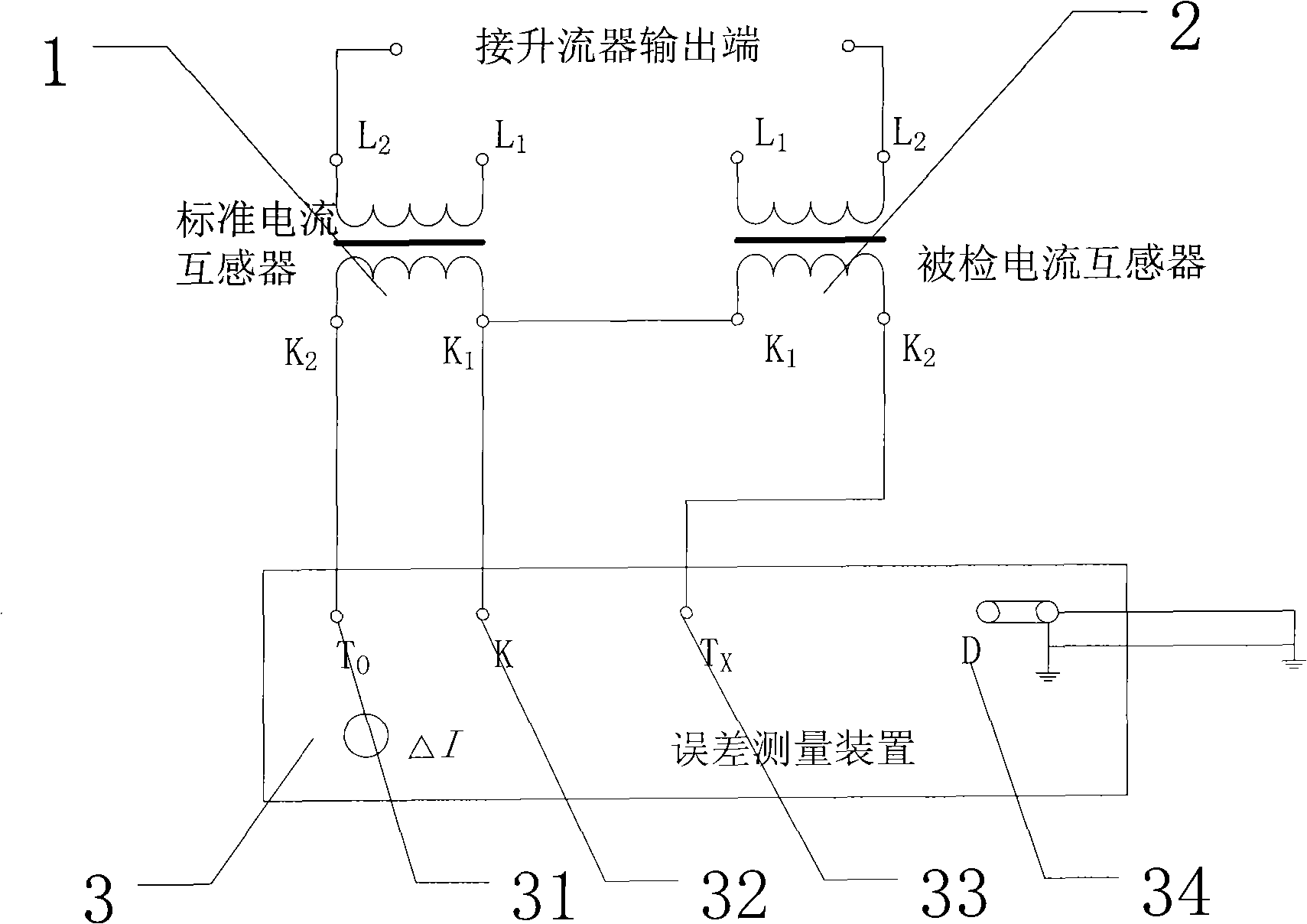
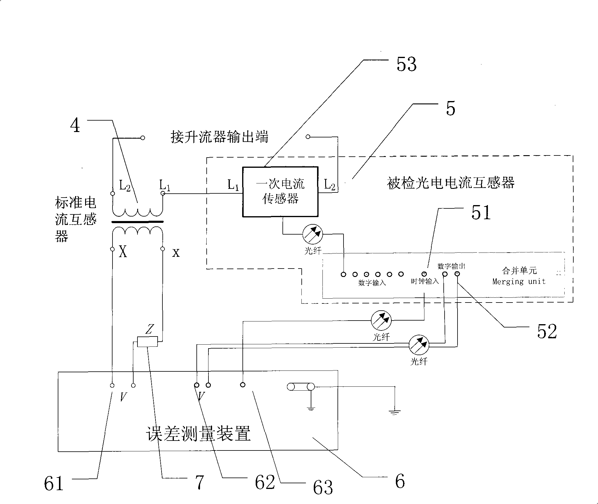
The invention relates to detection of the accuracy of an optical current transformer, in particular to a method for detecting the accuracy of the optical current transformer for measuring. The detection method comprises the following steps of appearance inspection, measurement of insulation resistance, testing of power frequency voltage, and error measurement, wherein the error measurement comprises the following steps: taking a standard current transformer as the reference; and connecting homonymous measuring ends of primary winding of the current transformer to be detected together, directly or indirectly grounding one end of output ends of a current amplifier according to different situations. The technical proposal is adopted, thereby radically solving the problem of the accuracy of the optical current transformer for measuring, and being capable of effectively carrying out the error measurement for the accuracy of the optical current transformer for measuring to control the error of the accuracy of the optical current transformer for measuring in an allowable range.

Description

technical field [0001] The invention relates to the accuracy detection of a photoelectric current transformer, in particular to a method for detecting the accuracy of a photoelectric current transformer for measurement. Background technique [0002] At present, electromagnetic current transformers are widely used in power systems, but with the development of power systems in the direction of large capacity and high voltage, digital measurement, protection, dispatch and control of factories, stations and systems have become a development trend. The requirements for miniaturization, intelligence, and high reliability of equipment are also getting higher and higher. The existing electromagnetic transformer can no longer meet this requirement due to its structural characteristics and existing deficiencies. [0003] Compared with the traditional electromagnetic induction current transformer, the photoelectric current transformer has the following series of advantages: [0004] ...

Claims


Application Information

Patent Timeline
IPC IPC(8): G01R35/00G01R15/18
Inventor 陈文中何维国王之浩林一
Owner SHANGHAI MUNICIPAL ELECTRIC POWER CO
Learn More