

Sending and using method of measure-reference signals
A technology for measuring reference signals and reference signals, applied in the field of communications, can solve the problem of no LTE-Advanced measurement reference signal transmission method, etc., and achieve the effects of improving overall performance, reducing reference signal overhead, and ensuring performance
- Summary
- Abstract
- Description
- Claims
- Application Information
AI Technical Summary
Problems solved by technology
Method used
Image

Examples
no. 1 example
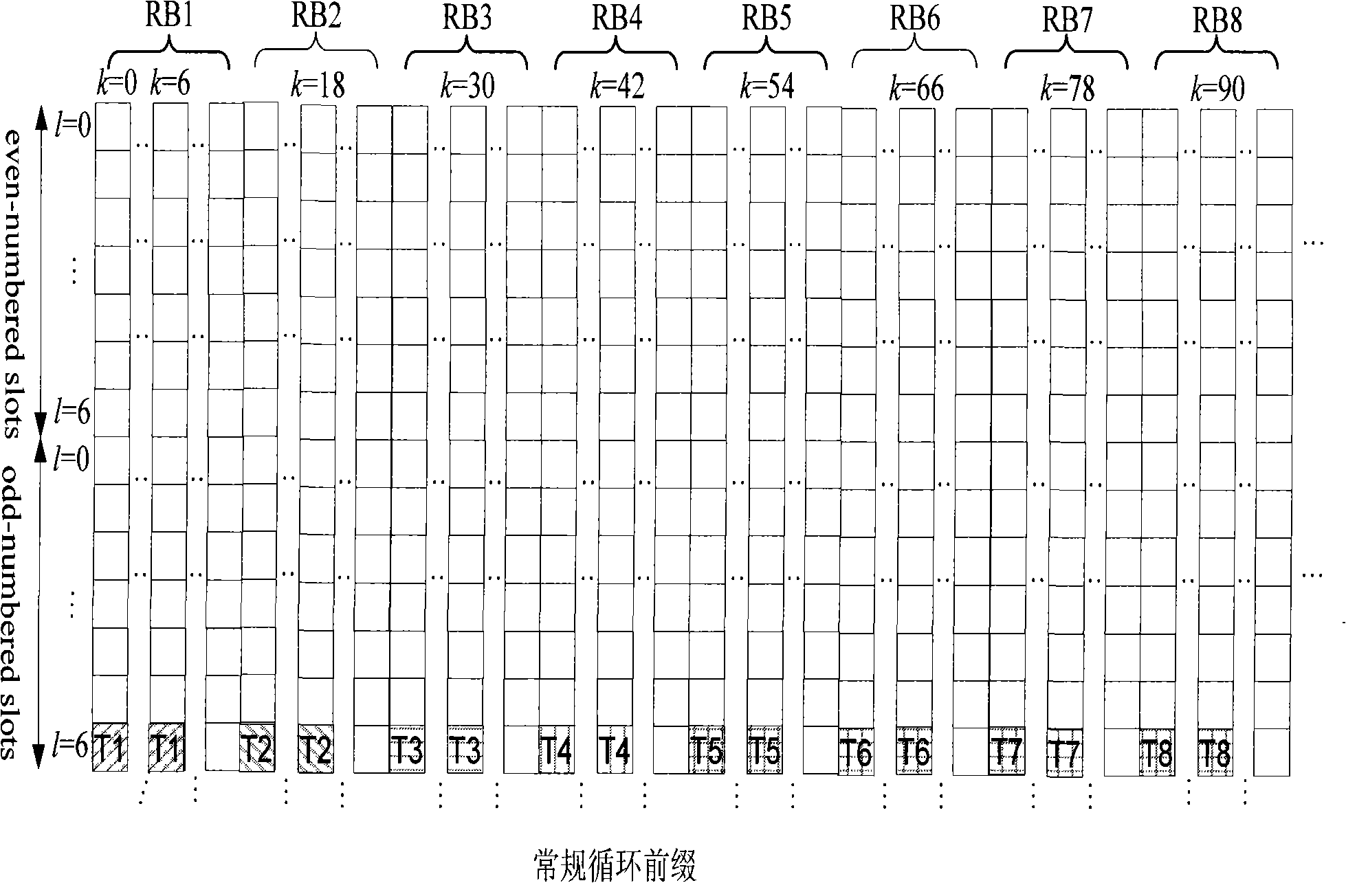
[0082] Fig. 2 is a schematic diagram of positions of measurement reference signals in physical resource blocks according to the first embodiment of the present invention. In the case where the cyclic prefix is a regular cyclic prefix, the position of the measurement reference signal in the physical resource block is as follows Figure 2a As shown, in the case where the cyclic prefix is an extended cyclic prefix, the position of the measurement reference signal in the physical resource block is as follows Figure 2b shown.
[0083] In this embodiment, assuming that the number of newly added measurement reference signals is 8, the measurement reference signals are divided into K=8 reference signal groups, and each reference signal group includes measurement reference signals of one antenna logic port. The eight reference signal groups are recorded as: {#0}, {#1}, {#2}, {#3}, {#4}, {#5}, {#6}, {#7}.
[0084] In addition, in this example, P 1 =P 2 =...=P K =P=P max .
...
no. 2 example
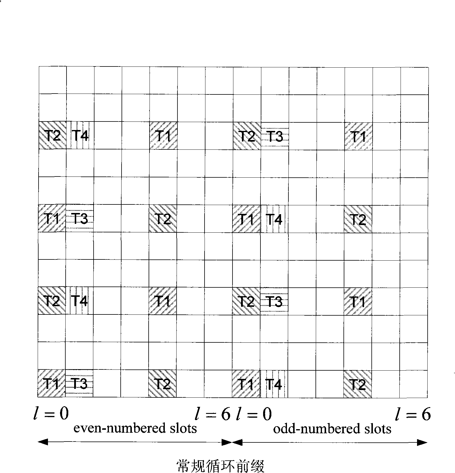
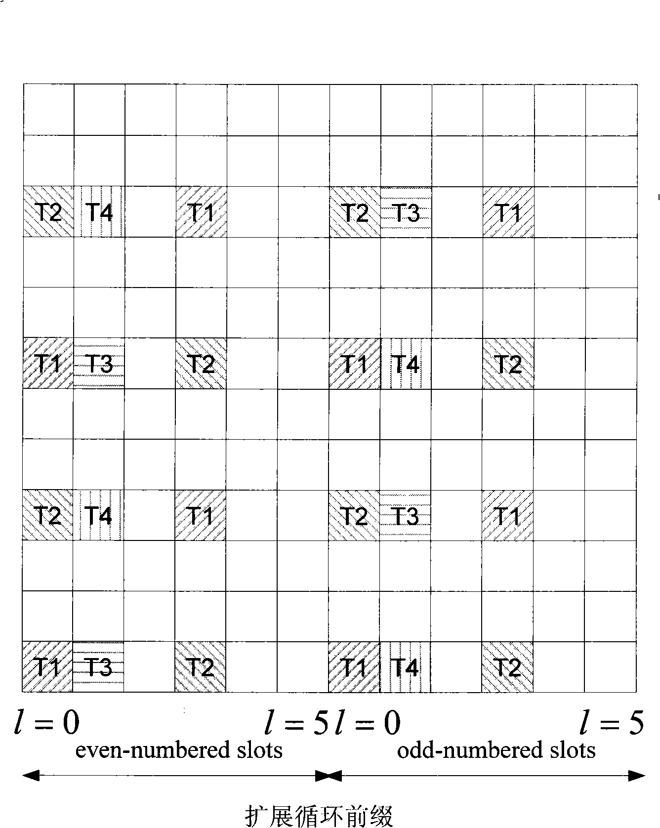
[0092] Fig. 3 is a schematic diagram of positions of measurement reference signals in physical resource blocks according to the second embodiment of the present invention. In the case where the cyclic prefix is a regular cyclic prefix, the position of the measurement reference signal in the physical resource block is as follows Figure 3a As shown, in the case where the cyclic prefix is an extended cyclic prefix, the position of the measurement reference signal in the physical resource block is as follows Figure 3b shown.
[0093] In this embodiment, assuming that the number of newly added measurement reference signals is 8, the measurement reference signals are divided into K=4 reference signal groups, and each reference signal group contains measurement reference signals of two antenna logic ports; the 4 The reference signal groups are recorded as: {#0, #1}, {#2, #3}, {#4, #5}, {#6, #7}.
[0094] In addition, in this example, P 1 =P 2 =...=P K =P=P max .
[0095]...
no. 3 example
[0102] Fig. 4 is a schematic diagram of positions of measurement reference signals in physical resource blocks according to the third embodiment of the present invention. In the case where the cyclic prefix is a regular cyclic prefix, the position of the measurement reference signal in the physical resource block is as follows Figure 4a As shown, in the case where the cyclic prefix is an extended cyclic prefix, the position of the measurement reference signal in the physical resource block is as follows Figure 4b shown.
[0103] In this embodiment, assuming that the number of newly added measurement reference signals is 8, the measurement reference signals are divided into K=4 reference signal groups, and each reference signal group contains measurement reference signals of two antenna logic ports; the 4 The reference signal groups are recorded as: {#0, #1}, {#2, #3}, {#4, #5}, {#6, #7}.
[0104] In addition, in this example, P 1 =P 2 =...=P K =P=P max .
[0105] ...
PUM
 Abstract
Description
Claims
Application Information