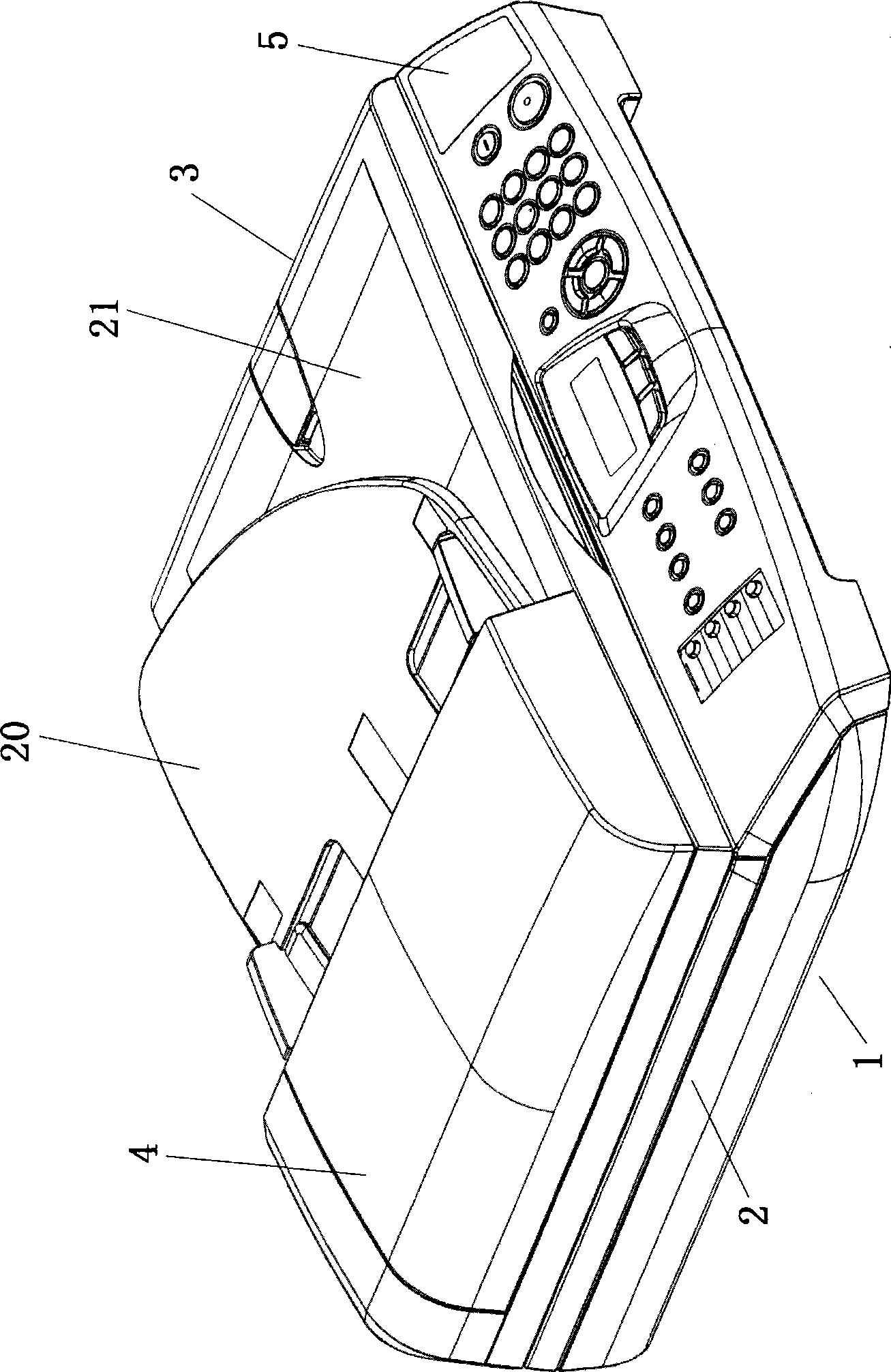
Recording sheet discharge device
A technology for recording sheets and discharge devices, which is applied in the directions of transportation and packaging, electrical components, and delivery items, and can solve problems such as increasing the number of parts, increasing the cost of raw materials, and complicating the assembly process
- Summary
- Abstract
- Description
- Claims
- Application Information
AI Technical Summary
Problems solved by technology
Method used
Image
Examples
no. 1 example
[0047] Next, the structures of the driving roller 26 and the driven roller 30 according to the first embodiment of the present invention will be described with reference to FIGS. 7 to 10 .
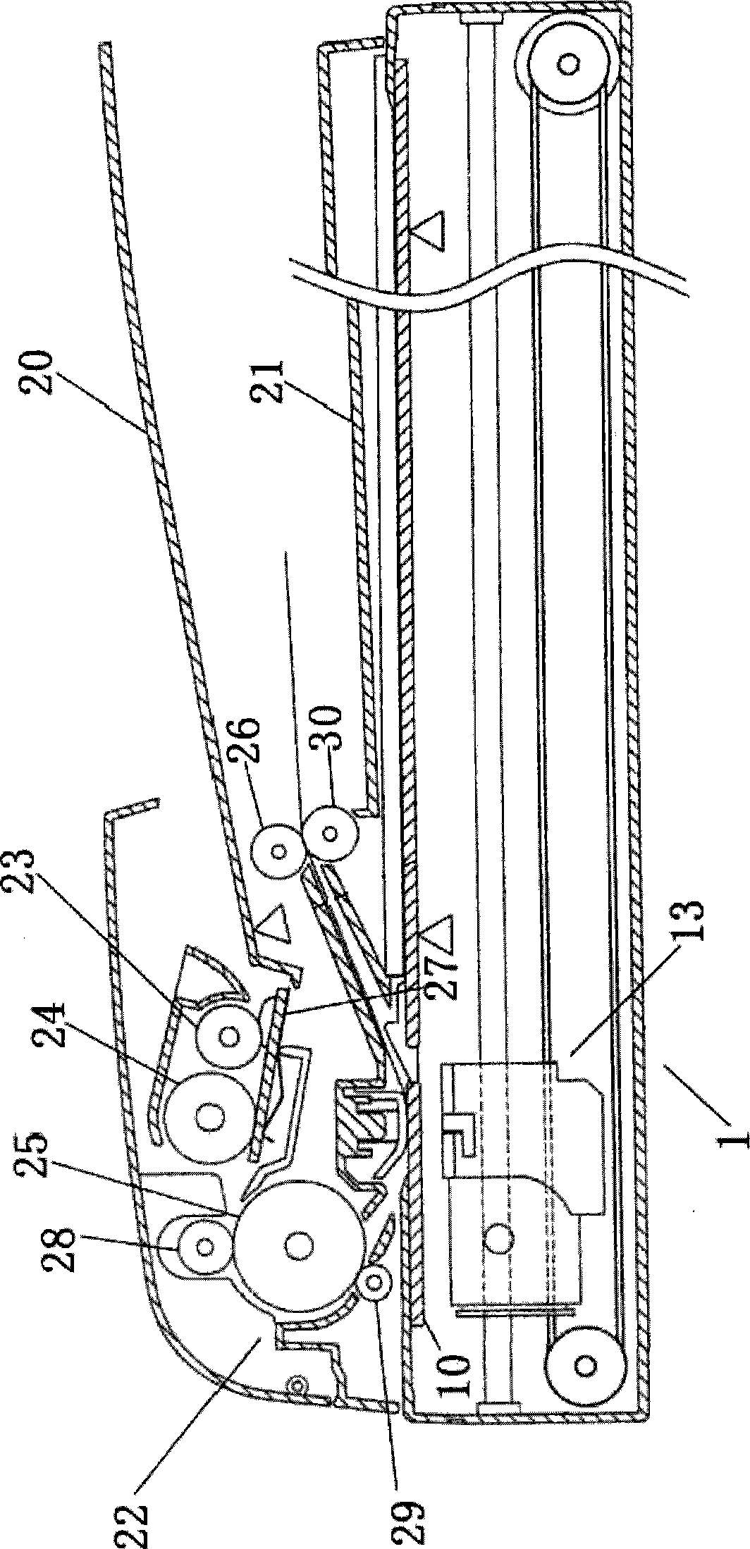
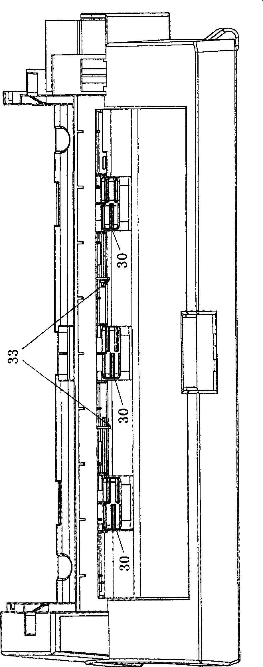
[0048] Figure 7(a) shows an enlarged perspective view of a driving roller and a driven roller according to a first embodiment of the present invention, and Figure 7(b) shows a front view of a driving roller and a driven roller according to a first embodiment of the present invention In the figure, the supporting frame 32 is cut off to cover a part of the driven roller shaft to clearly show the shaft portion of the driven roller. As shown in FIG. 7( a ) and FIG. 7( b ), the driving roller 26 and the driven roller 30 cooperate as main parts constituting the paper discharge device of the present invention. The driving roller 26 is placed on the upper side of the driven roller 30 and is fixed on the driving roller shaft 41. The driving roller shaft 41 is perpendicular to the paper discharge di...
no. 2 example
[0061] Fig. 11 (a) shows the perspective view of the driven roller according to the second embodiment of the present invention, Fig. 11 (b) shows the front view of the driven roller according to the second embodiment of the present invention, Fig. 11 (c) Shown is a side view of a driven roller according to a second embodiment of the present invention. Here, the same reference numerals are used for the same or corresponding components as in the first embodiment.
[0062] As shown in FIG. 11( a ), an annular groove 43 is arranged in the middle of the driven roller 30 around its axis, and the annular groove 43 divides the driven roller 30 into a left half and a right half along its axial direction. For the above-mentioned two parts of the roll section, six passage grooves are evenly distributed along its outer peripheral surface at equal intervals respectively, namely the left groove 42a and the right groove 42b. The depth of the grooves 42a, 42b is preferably the same as the dep...
no. 3 example
[0067] Fig. 12 (a) shows the perspective view of the driven roller according to the third embodiment of the present invention, Fig. 12 (b) shows the front view of the driven roller according to the third embodiment of the present invention, Fig. 12 (c) Shown is a cross-sectional view of a driven roller according to a third embodiment of the present invention, that is, a cross-sectional view along line E-E in FIG. 12(b).
[0068] As shown in FIG. 12( a ) and FIG. 12( b ), the peripheral surface of the driven roller 30 is formed by the surface of several protrusions 44 , and the part other than the protrusions 44 constitutes a concave portion. In the axial direction of the driven roller 30, the protrusions can be divided into seven protrusion groups, each protrusion group is equally spaced in the axial direction of the driven roller 30, each protrusion group includes four protrusions, each The protrusions are arranged at equal intervals at intervals of 90° on the circumference o...
PUM
 Abstract
Description
Claims
Application Information
 - R&D
- Intellectual Property
- Life Sciences
- Materials
- Tech Scout
- Unparalleled Data Quality
- Higher Quality Content
- 60% Fewer Hallucinations
Browse by: Latest US Patents, China's latest patents, Technical Efficacy Thesaurus, Application Domain, Technology Topic, Popular Technical Reports.
© 2025 PatSnap. All rights reserved.Legal|Privacy policy|Modern Slavery Act Transparency Statement|Sitemap|About US| Contact US: help@patsnap.com


