Injector

A technology of injectors and nozzles, which is applied in the direction of fuel injection devices, machines/engines, engine components, etc., can solve the problems of unavoidable costs, increased attractiveness, and rising costs, and achieve high efficiency and stable fuel injection. Controlling, attractive effect

Inactive Publication Date: 2012-05-30
DENSO CORP
View PDF7 Cites 0 Cited by
  • Summary
  • Abstract
  • Description
  • Claims
  • Application Information

AI Technical Summary

Problems solved by technology

Therefore, when the fuel pressure becomes higher due to high injection pressure, the attractive force required for the electromagnetic drive part becomes large, and the driving force required for valve opening cannot be sufficiently reduced.
Therefore, there are problems that the electromagnetic drive part is enlarged, and thus the cost increase cannot be avoided, or the needle valve cannot be opened and closed under high injection pressure due to limitations of the injector space and load current.

Method used


Image

  • Injector
  • Injector
  • Injector

Examples


no. 1 approach

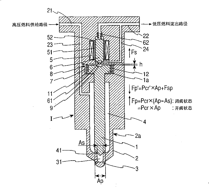
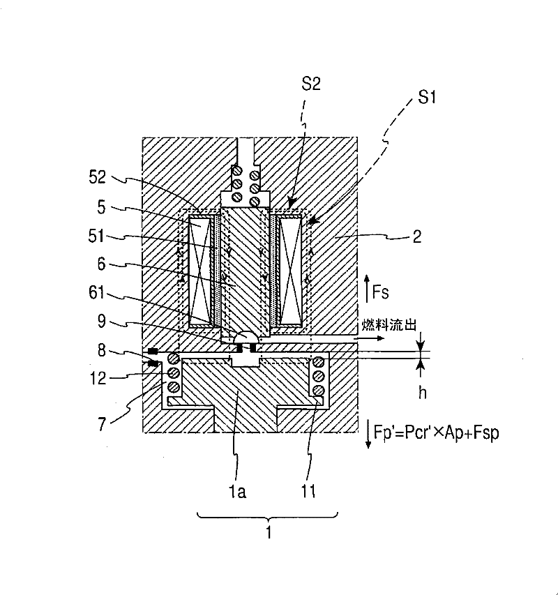
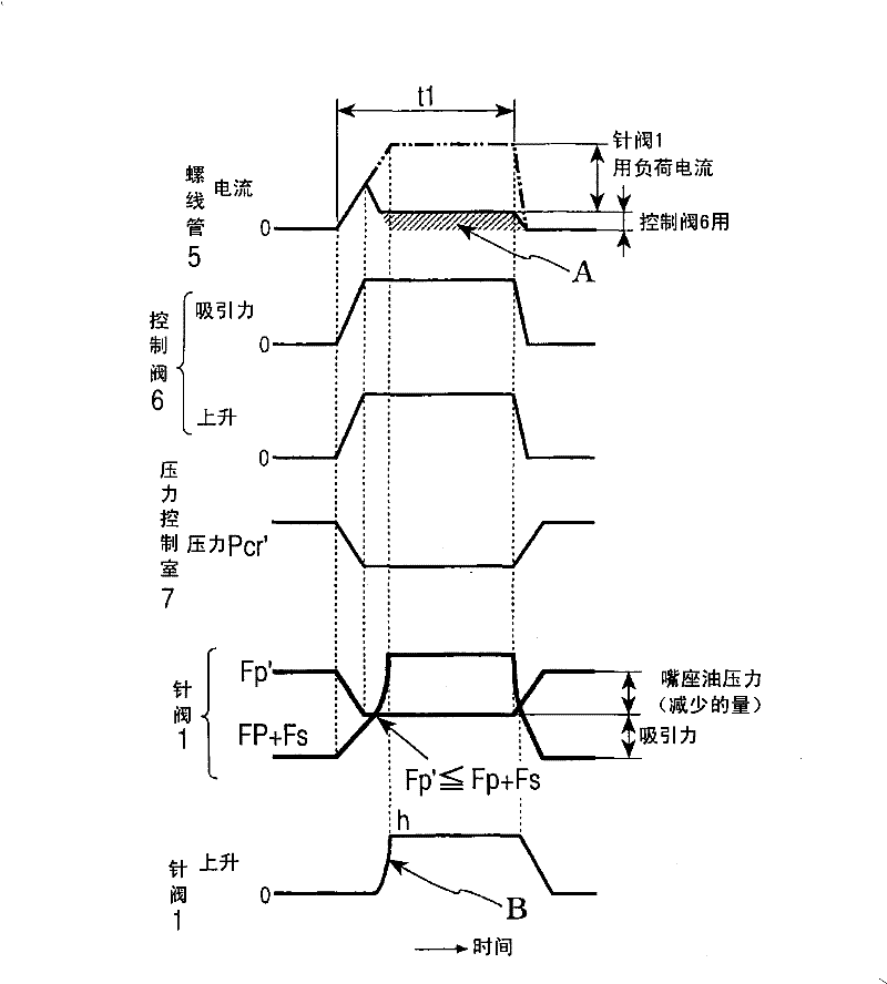
[0051] figure 1 It is an overall sectional view showing the general structure of the injector 1 of the present invention, figure 2 is an enlarged cross-sectional view showing its main part structure, image 3 It is a timing chart showing an example of fuel injection control.

[0052] The injectors 1 are applied to, for example, an accumulator fuel injection device for a diesel engine, and are provided one-to-one for each cylinder of the internal combustion engine. In a common rail (not shown) that is a pressure accumulator common to each injector I, fuel pressurized to a high pressure by a high-pressure feed pump (not shown) is accumulated, and the control device (ECU, not shown) controls the The entire device is controlled so as to obtain the optimum injection amount and injection timing corresponding to the operating state of the internal combustion engine. As the fuel to be pressurized in the common rail, liquefied fuel such as dimethyl ether (DME) or liquefied petroleu...


PUM


Abstract

The invention relates to an injector, wherein a needle valve is accommodated in the main body in rod shape, an armature portion is integrally disposed at the base portion of the needle valve, and can be attracted by a solenoid of an electromagnetic driving portion, the control valve switches on and off between the pressure control chamber and the low pressure fuel outflow path. Applying the back pressure of the pressure control chamber to the armature portion, when the back pressure of the pressure control chamber is lowered to a predetermined pressure due to attracting and driving the control valve by the solenoid, the needle valve is raised by attraction of the solenoid.

Description

technical field [0001] The present invention relates to an injector for a fuel injection device of an internal combustion engine, in particular to a direct-acting injector. Background technique [0002] For example, as a diesel engine application, there is known an accumulator-type fuel injection device in which high-pressure fuel is accumulated in a common rail common to each cylinder. In the past, the injector of the pressure accumulator fuel injection device used: the high-pressure fuel supplied from the common rail is supplied to the injection hole, and supplied to the back pressure chamber of the needle valve that opens the injection hole, and the electromagnetic control valve of the three-way valve structure is used. Control the pressure of the back pressure chamber. The electromagnetic control valve accommodates the valve body in the valve chamber communicated with the back pressure chamber, and the valve body is driven by the solenoid so that the valve chamber is se...

Claims


Application Information

Patent Timeline
Patent Type & Authority Patents(China)
IPC IPC(8): F02M51/06
Inventor 关岛仁加藤正明
Owner DENSO CORP
Why Eureka
Try Eureka