Normally closed electromechanical compound high pressure oil pump

A high-pressure fuel pump, normally closed technology, applied in mechanical equipment, engine components, fuel injection pumps, etc., can solve the problems of fuel injector damage, poor safety, and the inability of high-pressure fuel pumps to complete emergency fuel supply work, achieving flexible control, The effect of improving safety

Active Publication Date: 2018-01-19
HARBIN ENG UNIV
View PDF5 Cites 0 Cited by
  • Summary
  • Abstract
  • Description
  • Claims
  • Application Information

AI Technical Summary

Problems solved by technology

However, the common normally open electronically controlled high-pressure oil pump has the following disadvantages: first, when the solenoid valve cannot be powered on due to a fault such as a power failure of the engine, the oil discharge circuit of the high-pressure oil pump is in a normally open state, and the high-pressure oil pump cannot complete the emergency oil supply work; Second, when the solenoid valve is stuck in the closed state, the oil pressure in the valve will continue to rise, causing adverse effects on the solenoid valve and the fuel injector, causing damage to other hydraulic devices such as the fuel injector; When there is any failure but the oil supply is still available, the high-pressure oil pump cannot complete the adjustment of the oil supply time and quantity
In short, the traditional electronically controlled high-pressure oil pump has poor safety, does not have the ability to respond to failures in an emergency, and cannot meet the requirements of engine stability and safety.

Method used


Image

  • Normally closed electromechanical compound high pressure oil pump
  • Normally closed electromechanical compound high pressure oil pump
  • Normally closed electromechanical compound high pressure oil pump

Examples


Embodiment Construction

[0014] The present invention is described in more detail below in conjunction with accompanying drawing example:

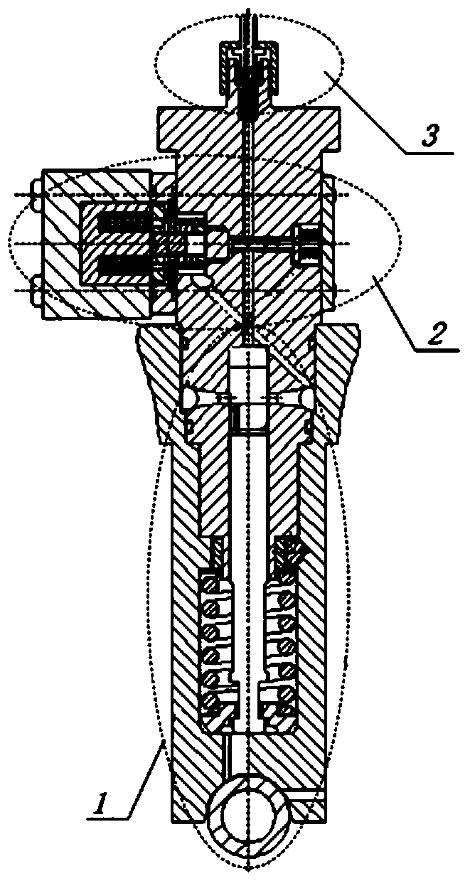
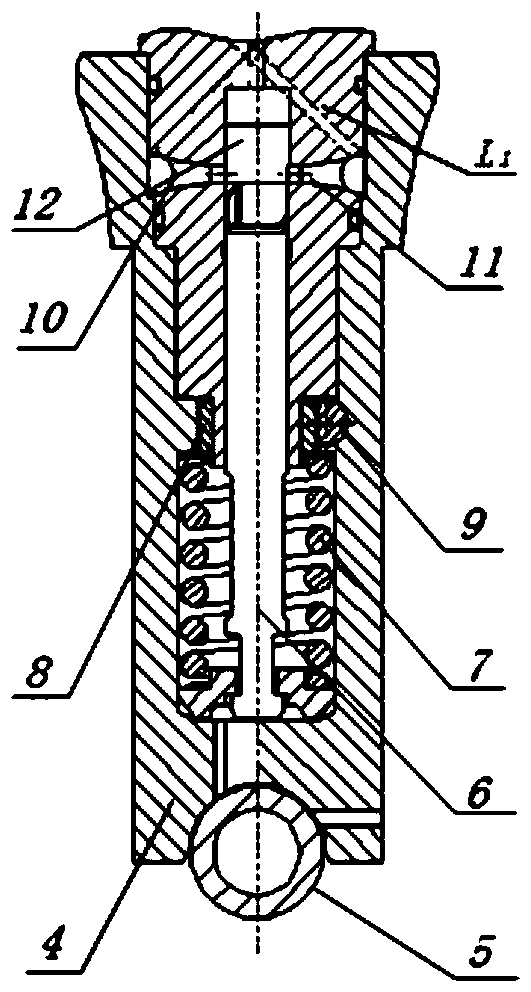
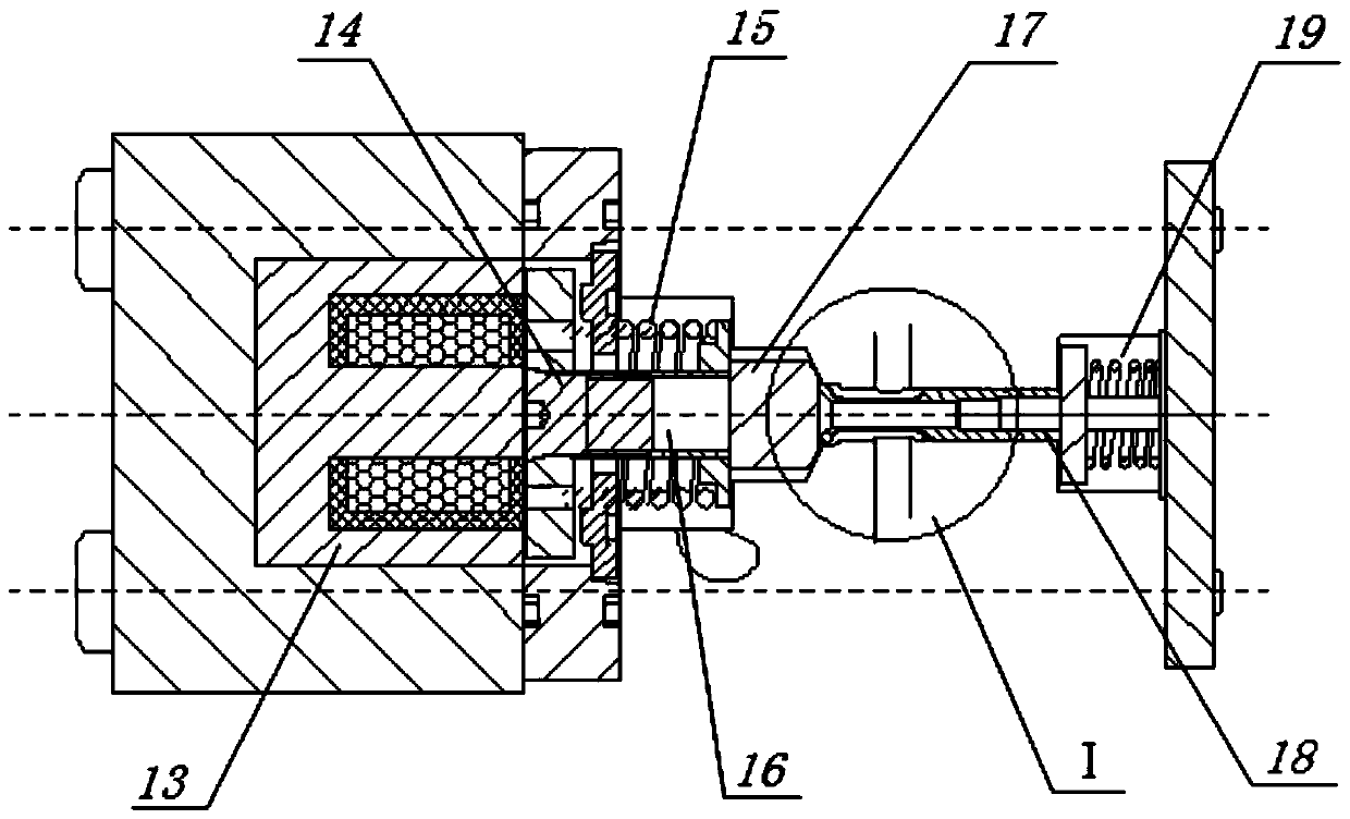
[0015] combine Figure 1~4 , The device includes a roller plunger 1, a normally closed fuel control valve 2 and an oil outlet valve 3. The roller plunger 1 is installed at the bottom of the pump body 4, and is composed of a roller 5, a plunger 6, a plunger spring 7, a ring gear 8, a gear rod 9, an oil inlet 10, an oil return hole 11 and a plunger chamber 12. A normally closed fuel control valve is installed above the plunger chamber 12, including a solenoid valve 13, a solenoid valve stem 14, a solenoid valve spring 15, an oil drain cone valve connecting sleeve 16, an oil drain cone valve 17, and an oil drain cone valve Valve stem 18 and oil discharge cone valve spring 19. The oil outlet valve 5 is installed on the top of the pump body 1 and consists of an oil outlet valve spring 22 and a high-pressure oil pipe connection port 23 .

[0016] When the solenoid va...


PUM


Abstract

The object of the present invention is to provide a normally closed electromechanical composite high-pressure oil pump, including a roller plunger, a normally closed fuel control valve and an oil outlet valve. The roller plunger is installed at the bottom of the pump body and consists of a roller, plunger, plunger spring, ring gear, gear rod, oil inlet hole, oil return hole and plunger chamber, and the plunger is designed with a spiral groove. The normally closed fuel control valve is installed above the plunger, including solenoid valve, solenoid valve stem, solenoid valve spring, oil drain poppet valve connecting sleeve, oil drain poppet valve, oil drain poppet valve stem and oil drain poppet valve spring . The normally closed fuel control valve is closed when it is not powered on, and the oil drain poppet valve opens the oil drain circuit when it is powered on. The invention improves the reliability of engine hydraulic systems such as high-pressure oil pumps and fuel injectors, and improves the stability of engine operation. By changing the size and form of the electromagnetic force of the fuel control solenoid valve, different fuel supply timing, fuel supply time and fuel supply volume requirements of the engine under different operating conditions and different loads can be realized.

Description

technical field [0001] The invention relates to a fuel injection device, in particular to an engine fuel injection device. Background technique [0002] The two serious problems faced by mankind in today's society are energy shortage and environmental pollution. Engines are widely used in domestic industries due to their high power, long life and good power performance. However, the traditional technology engine is gradually eliminated due to its shortcomings of high energy consumption and high emission, and the research on an engine with less energy consumption, high efficiency and good emission performance has become an inevitable trend of engine development. In recent years, the development of electronic control technology has provided technical support for the innovation of engine technology, and the electronic control fuel system of the engine has become the main means to solve engine problems. The electronically controlled high-pressure fuel pump is an important techn...

Claims


Application Information

Patent Timeline
Patent Type & Authority Patents(China)
IPC IPC(8): F02M59/36F02M59/46
Inventor 范立云闫昕白云扈爽赵建辉马修真宋恩哲
Owner HARBIN ENG UNIV
Why Eureka
Try Eureka