A method for controlling a fuel supply system

A fuel input and fuel technology, applied in electrical control, engine control, fuel injection control, etc., can solve problems such as the inability to achieve closed-loop operation or closed-loop control of BLDC motors, problems with motor starting and operation, and the inability of the rotor to follow the rectifier. The effect of shortening the waiting time, avoiding the start-up delay, avoiding the delay

Inactive Publication Date: 2017-07-28
ROBERT BOSCH GMBH
View PDF6 Cites 0 Cited by
  • Summary
  • Abstract
  • Description
  • Claims
  • Application Information

AI Technical Summary

Problems solved by technology

This leads to problems with starting and working of the motor under normal conditions, i.e. the conditions normally present when the motor is started
[0007] The characteristic curves are based on normal conditions, however, when conditions significantly different from these normal conditions exist, disturbances occur so that the motor cannot be started, or comes to a standstill after a short period of actuation
This is the case, for example, when the torque required by the electric

Method used


Image

  • A method for controlling a fuel supply system
  • A method for controlling a fuel supply system

Examples


Embodiment Construction

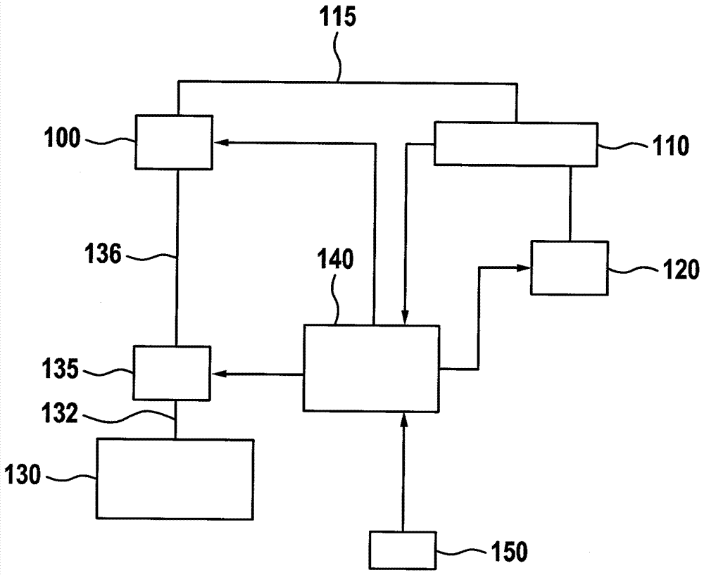
[0030] figure 1Shown in is a block diagram of a preferred embodiment of the fuel input system of the present invention. Use 100 to represent the high pressure pump. The high-pressure pump conveys fuel from the low-pressure region into the high-pressure region. This high-pressure area essentially contains a high-pressure accumulator 110 , known as a pressure accumulator, and a high-pressure inlet line 115 contained between the high-pressure pump 100 and the high-pressure accumulator 110 . Fuel enters the combustion chamber of the internal combustion engine from the high-pressure accumulator 110 via the injector 120 .

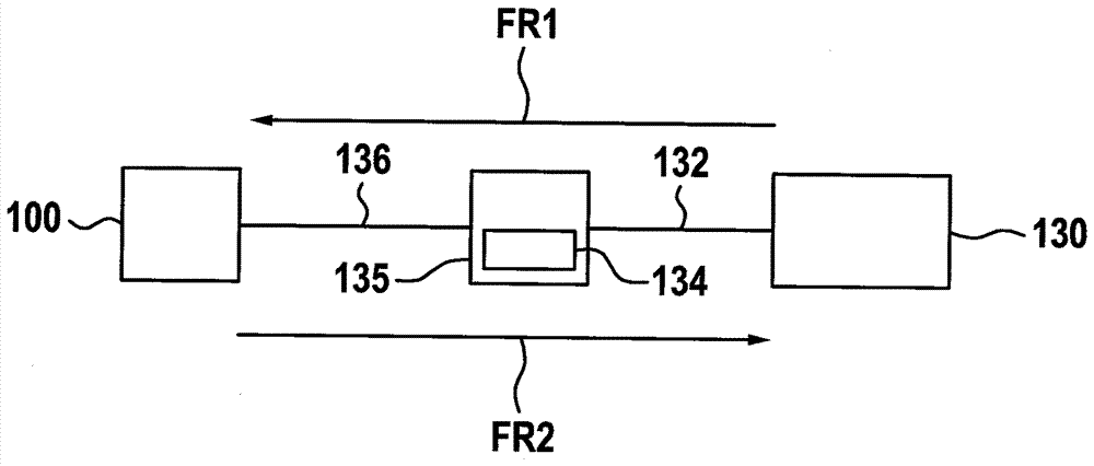
[0031] Furthermore, the high-pressure pump 100 is connected to a low-pressure area which essentially contains a low-pressure accumulator 130 , also called a tank. In addition, this low-pressure region contains fuel pump 135 , which in the embodiment described is designed as a low-pressure fuel pump. Specifically, the low pressure fuel pump 135 is driven by a ...


PUM


Abstract

The invention relates to a method for controlling a fuel supply system. In the method, a fuel pump (135) is controlled such that the fuel pump (135), during a supply operation period, conveys fuel in a first conveying direction (FR1). The fuel pump (135) is controlled after the supply operation is finished such that the fuel pump (135) conveys the fuel in a second conveying direction (FR2) opposite to the first conveying direction (FR1).

Description

technical field [0001] The invention relates to a method and a controller for controlling a fuel feed system as well as to a computing unit and a computer program for carrying out the method according to the invention. Background technique [0002] From DE 10 2013 213 924 A1 a method is known for controlling a fuel feed system which is equipped with a low-pressure region and a high-pressure region, wherein a valve is provided between the low-pressure region and the high-pressure region, and according to which valve to control the fuel pump provided in this low-pressure region. [0003] The fuel pump arranged in the low-pressure region can be designed as an electric fuel pump driven by an electric motor (also called “electrical gear pump” or “eGP” in English). In the sense of low production costs and a long service life or durability, electric motors, in particular brushless DC motors (Brushless (brushless) DC motors, BLDC motors), which are designed brushless and sensorless...

Claims


Application Information

Patent Timeline
IPC IPC(8): F02D41/30F02D41/38
CPCF02D41/3082F02D41/3854F02D41/062F02D41/3863F02D2200/0602
Inventor J.亚历克尔
Owner ROBERT BOSCH GMBH
Why Eureka
Try Eureka