Fuel injector nozzle assembly having Anti-cavitation vent and method

a fuel injector and nozzle technology, which is applied in the direction of fuel injection apparatus, machine/engine, feed system, etc., can solve the problems of limited cavitation bubble production in the spring cavity, reduce the pressure of fuel, and reduce the production of cavitation bubbles in the spring cavity. , the effect of reducing the pressure of fuel

Active Publication Date: 2020-12-17
PROGRESS RAIL SERVICES
View PDF0 Cites 0 Cited by
  • Summary
  • Abstract
  • Description
  • Claims
  • Application Information

AI Technical Summary

Benefits of technology

[0006]In still another aspect, a method of operating a fuel injector for an internal combustion engine includes increasing a pressure of fuel in a nozzle cavity in the fuel injector, actuating an outlet check in the fuel injector to an open position in response to the increased pressure of fuel in the nozzle cavity, and displacing fuel in a spring cavity in the fuel injector to a low pressure space in response to positioning the outlet check at the open position. The method further includes reducing a pressure of fuel in the nozzle cavity, and commencing actuating the outlet check back to a closed position in response to the reduction in the pressure of fuel in the nozzle cavity using a biasing spring in the fuel injector. The method still further includes returning fuel to the spring cavity from the low pressure space in response to the commencing of the actuating of the outlet check back to the closed position, and conveying the returning fuel to the spring cavity through an anti-cavitation vent in the fuel injector such that production of cavitation bubbles in the spring cavity is limited.

Problems solved by technology

The method still further includes returning fuel to the spring cavity from the low pressure space in response to the commencing of the actuating of the outlet check back to the closed position, and conveying the returning fuel to the spring cavity through an anti-cavitation vent in the fuel injector such that production of cavitation bubbles in the spring cavity is limited.

Method used


Image

  • Fuel injector nozzle assembly having Anti-cavitation vent and method
  • Fuel injector nozzle assembly having Anti-cavitation vent and method
  • Fuel injector nozzle assembly having Anti-cavitation vent and method

Examples


Embodiment Construction

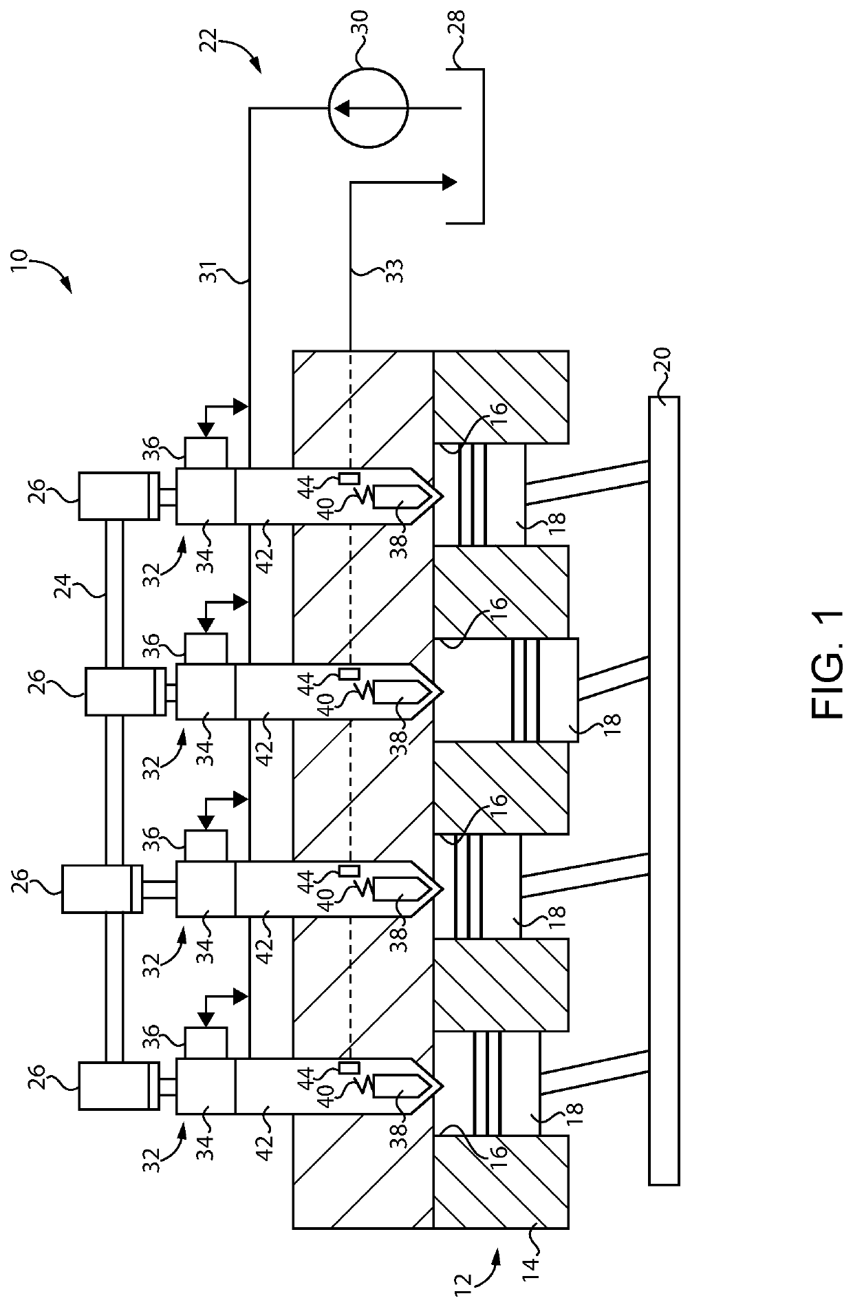
[0016]Referring to FIG. 1, there is shown an internal combustion engine system 10 according to one embodiment and including an internal combustion engine 12 having an engine housing 14 with a plurality of cylinders formed therein. Cylinders 16 may be in any suitable arrangement such as a V-pattern, an in-line pattern, or still another. A plurality of pistons 18 are each positioned within one of cylinders 16 and movable between a bottom dead center position and a top dead center position in a conventional four-cycle or two-cycle pattern. Engine 12 can include a compression ignition internal combustion engine where pistons 18 increase a pressure within cylinders 16 to an autoignition threshold for fuel and air. Pistons 18 are coupled with a crankshaft 20 in a generally conventional manner. Engine 12 may be structured to operate on a suitable compression ignition fuel such as diesel distillate fuel, biodiesel, blends of these, or still others. Engine system 10 further includes a fuel s...


PUM


Abstract

A nozzle assembly for a fuel injector includes an injector housing having a casing and a stack within the casing, an outlet check movable within a nozzle cavity in the injector housing, and having a stop positioned within a stop cavity. A clearance is formed between the outlet check and the injector housing and fluidly connects a spring cavity to a stop cavity, and an anti-cavitation vent is formed in the stack and fluidly connects the spring cavity to a low pressure space. The anti-cavitation vent limits pressure changes in the spring cavity during fuel injection such that production of cavitation bubbles in the spring cavity is limited.

Description

TECHNICAL FIELD[0001]The present disclosure relates generally to a fuel injector for an internal combustion engine, and more particularly to a fuel injector nozzle assembly having an anti-cavitation vent for a spring chamber.BACKGROUND[0002]Fuel injectors have been used in a great many different types of internal combustion engines for over a century. In many modern designs, a valve member commonly referred to as an outlet check or by similar terms is positioned within a fuel injector housing, and operated to connect high pressure fuel in an internal fuel passage, or in an external fuel supply, with fuel spray orifices in fluid communication with a combustion chamber. Some outlet check designs are directly controlled, where hydraulic pressure is selectively applied and relieved upon a closing hydraulic surface of the outlet check, to enable pressurized fuel to actuate the outlet check open and selectively inject fuel into the combustion chamber. Other designs are not directly contro...

Claims


Application Information

Patent Timeline
Patent Type & Authority Applications(United States)
IPC IPC(8): F02M57/02F02M61/18F02M45/06
CPCF02M45/066F02M61/18F02M57/023F02M63/001F02M59/366F02M2200/04
Inventor LOPEZ, ROLANDOPOTLURU, PITCHAIAHSCHLAIRET, EDWARD
Owner PROGRESS RAIL SERVICES
Why Eureka
Try Eureka