

Capacitive inductive faucet
A capacitive, inductive joint technology, applied in electric controllers, controllers with pulse train output signals, valve details, etc., can solve the problem of water accumulation, limited sensing angle of the sensing window, and sensitive probes susceptible to moisture. and other problems, to achieve the effect of rapid response and reliable induction
- Summary
- Abstract
- Description
- Claims
- Application Information
AI Technical Summary
Problems solved by technology
Method used
Image

Examples
Embodiment Construction
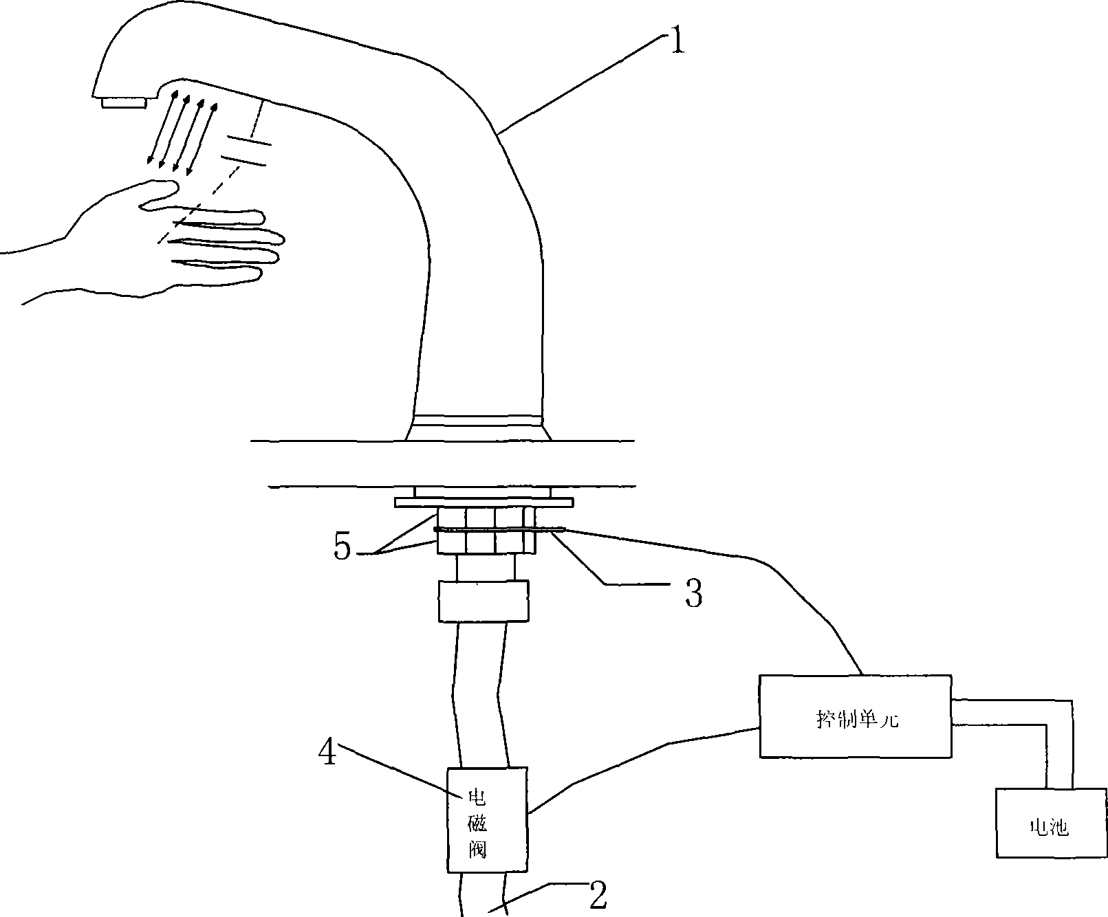
[0014] Such as figure 1 As shown in , the present invention includes a faucet body 1, a water inlet pipe 2 and a solenoid valve 4 arranged on the water inlet pipe, and also includes an induction joint 3 electrically connected to the faucet body, and the induction joint is fixedly arranged on the faucet body through a nut 5 The base of the body 1 is connected to a control unit.
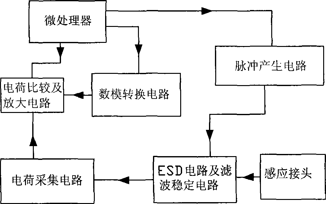
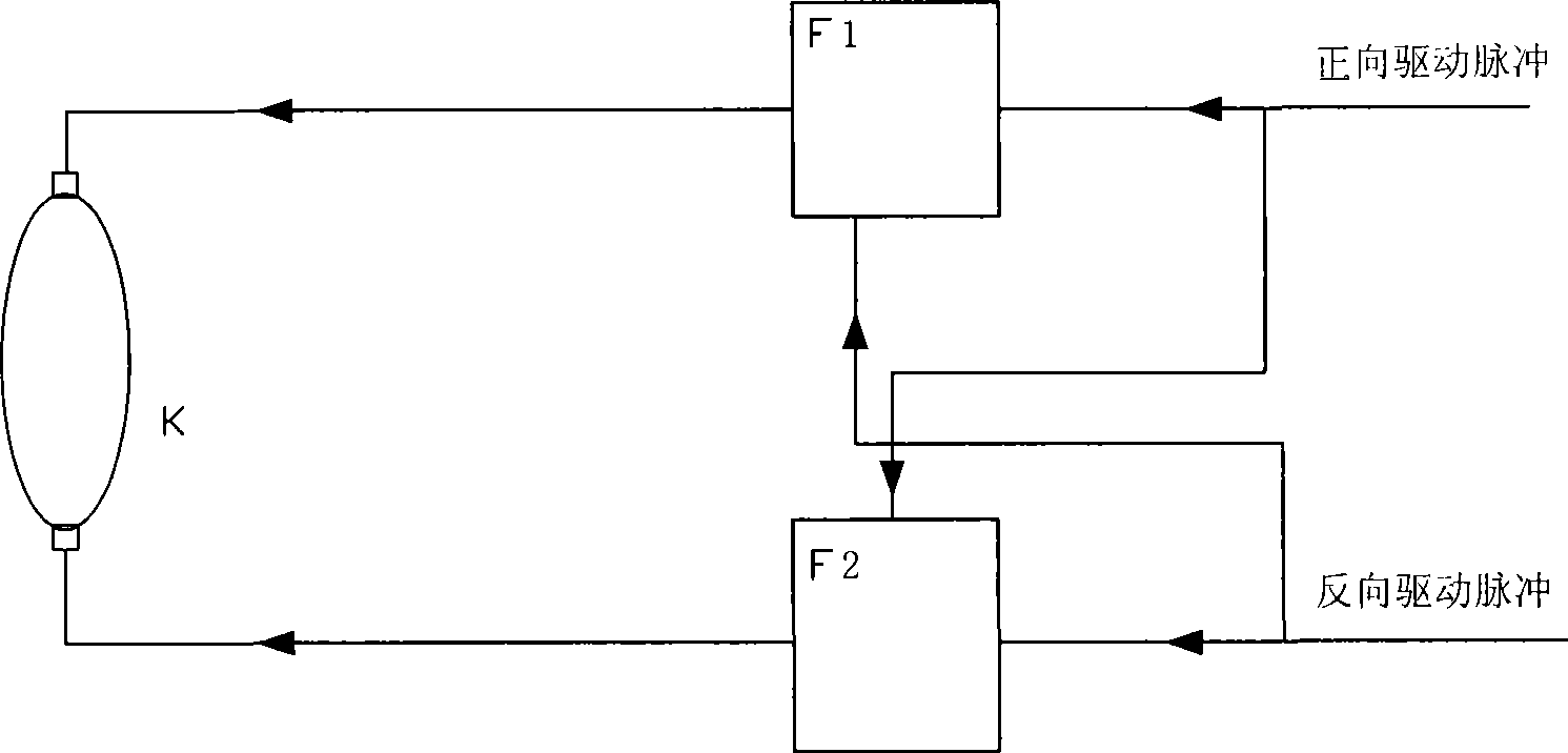
[0015] Such as figure 2 As shown in , the control unit includes a microprocessor, and the microprocessor controls a pulse generating circuit composed of a logic matrix to generate a pulse signal, which is sent to the sensing joint after filtering and stabilizing the circuit, and the sensing joint will sense After the charge change of the faucet body is processed by the electrostatic discharge circuit (ESD circuit for short) and the filter stabilization circuit, it is collected by the charge acquisition circuit and sent to the charge comparison and amplification circuit, and the amplified signal is se...
PUM
 Abstract
Description
Claims
Application Information