Novel mechanical remote water meter

A remote water meter and mechanical technology, applied in the field of new mechanical remote water meters, can solve the problems of difficult to observe the precise position of the pointer, inconvenient on-site observation and reading, and inability to display the counting axis, and achieve reliable and effective induction and simple appearance. , the effect of long life

Inactive Publication Date: 2016-09-21
TIANJIN BINGHUA ENERGY TECH
View PDF8 Cites 0 Cited by
  • Summary
  • Abstract
  • Description
  • Claims
  • Application Information

AI Technical Summary

Problems solved by technology

The existing magnetic sensor installation structure occupies almost 1 / 3 of the area of ​​the dial, causing a large area of ​​the dial to be blocked, which brings great inconvenience to the on-site observation and reading
Moreover, since the magnetic sensor outside the watch glass will inevitably block a counting axis below it, the counting axis cannot be fully displayed like the other counting axes
If it is still indicated by installing a pointer at the end of the counting shaft and making a scale on the concentric outer peripheral dial of the pointer, it is difficult to observe the hidden scale and the precise position of the pointer

Method used


Image

  • Novel mechanical remote water meter
  • Novel mechanical remote water meter
  • Novel mechanical remote water meter

Examples


Embodiment Construction

[0023] In order to further understand the content, characteristics and effects of the present invention, the following examples are given, and detailed descriptions are given below with reference to the accompanying drawings. It should be noted that this embodiment is descriptive, not restrictive, and cannot thereby limit the protection scope of the present invention.

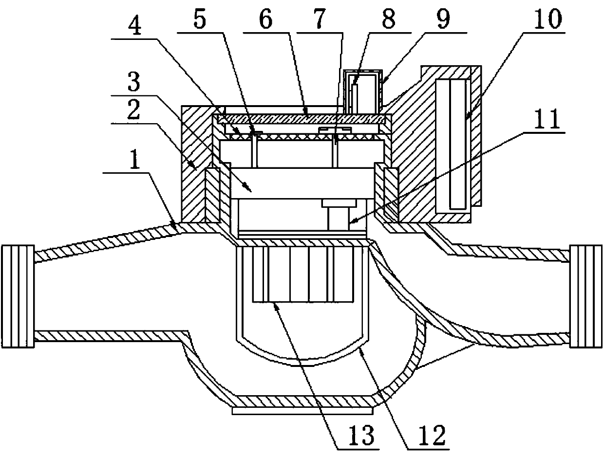
[0024] A new type of mechanical remote water meter, which is composed of a rotor water meter, a control unit and a waterproof interface. Box 13, impeller, impeller shaft 11 constitute, indicating mechanism is mainly made up of dial 4, counting shaft group, transmission gear group 3, and control unit is mainly made up of casing 2, sensor mechanism 9 and control module 10.

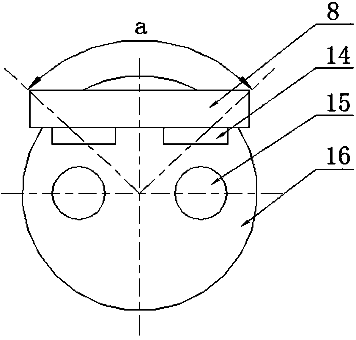
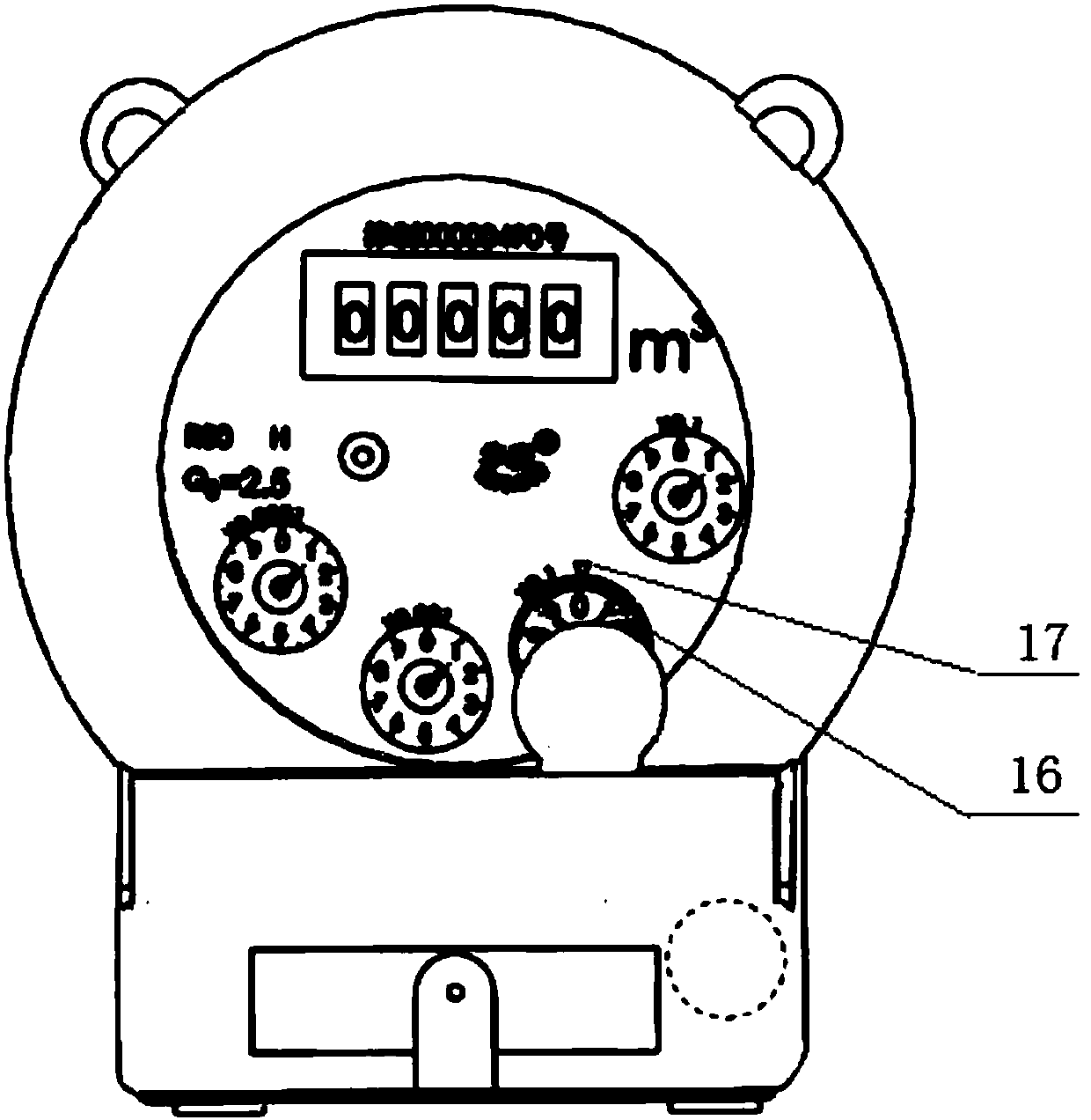
[0025] The counting axis group includes an induction counting axis 7 equipped with a magnet and three to five pointer counting axes 5 equipped with pointers. Two magnets 15 are installed on the induction counting axis, and a sensor mechanism ...


PUM


Abstract

A novel mechanical remote water meter is composed of a rotating vane type water meter body, a control unit and a waterproof connector. A metering mechanism of the rotating vane type water meter body is mainly composed of an impeller box, an impeller and an impeller shaft. A counting shaft set of an indicating mechanism comprises an induction counting shaft and three to five pointer counting shafts, wherein the induction counting shaft is provided with two magnets. A sensor mechanism is installed on the exterior of meter glass, a PCB of the sensor mechanism is placed in a magnetic shielding case and vertically installed, two magneto-dependent sensors are vertically fixed to the PCB, a vertical plane where the PCB is located and the middle point of a connecting line of the two magnets are arranged in an off-center mode, a vertical plane where the two magneto-dependent sensors are located is parallel to any diameter part of a circumference formed by the two magnets, the distance between one magneto-dependent sensor and the center of the connecting line of the two magnets is equal to the distance between the other magneto-dependent sensor and the center of the connecting line of the two magnets, and the waterproof connector is connected with a control module and is guided out. A non-contact magnetic sensing counting mechanism is adopted, precise counting can be achieved, shielding on a dial can be reduced to the maximum extent, and installation and observation are easy.

Description

technical field [0001] The invention belongs to the technical field of water meters, in particular to a novel mechanical remote water meter. Background technique [0002] Most of the existing automatic counting water meters are photoelectric direct-reading water meters. It can read the value of the water meter through the internal photoelectric system, so as to realize the remote reading. However, there are many problems in the existing photoelectric direct-reading water meter. First of all, its electronic control system must be integrated inside the water meter, which is difficult to process. Once water enters during use, it will cause damage to the circuit board. Moreover, the existence of factors such as light and air bubbles will affect the accuracy and reliability of the photoelectric reading of the electronic control system. [0003] At present, there are also magnetic induction mechanical remote water meters. It achieves electronic counting through the cooperatio...

Claims


Application Information

Patent Timeline
Patent Type & Authority Applications(China)
IPC IPC(8): G01F15/06G01F15/075G01F1/28G01F15/00
CPCG01F1/28G01F15/00G01F15/061G01F15/075
Inventor 张炳华
Owner TIANJIN BINGHUA ENERGY TECH
Why Eureka
Try Eureka