Mechanical remote water meter provided with novel magnetic sensing counting structure

A remote water meter and mechanical technology, applied in the direction of volume/mass flow generated by electromagnetic effect, volume/mass flow generated by mechanical effect, volume measurement, etc., can solve the problem that it is difficult to observe the precise position of the pointer and the inconvenience of on-site observation and reading , the counting axis cannot be displayed, etc., to achieve the effect of accurate counting, reliable and effective sensing, and simple appearance

Inactive Publication Date: 2016-10-26
TIANJIN BINGHUA ENERGY TECH
View PDF8 Cites 3 Cited by
  • Summary
  • Abstract
  • Description
  • Claims
  • Application Information

AI Technical Summary

Problems solved by technology

The existing magnetic sensor installation structure occupies almost 1 / 3 of the area of ​​the dial, causing a large area of ​​the dial to be blocked, which brings great inconvenience to the on-site observation and reading
Moreover, since the magnetic sensor outside the watch glass will inevitably block a counting axis below it, the counting axis cannot be fully displayed like the other counting axes
If it is still indicated by installing a pointer at the end of the counting shaft and making a scale on the concentric outer peripheral dial of the pointer, it is difficult to observe the hidden scale and the precise position of the pointer

Method used


Image

  • Mechanical remote water meter provided with novel magnetic sensing counting structure
  • Mechanical remote water meter provided with novel magnetic sensing counting structure
  • Mechanical remote water meter provided with novel magnetic sensing counting structure

Examples


Embodiment Construction

[0020] The present invention will be described in further detail below in conjunction with the accompanying drawings. The following embodiments are only descriptive, not restrictive, and cannot limit the protection scope of the present invention.

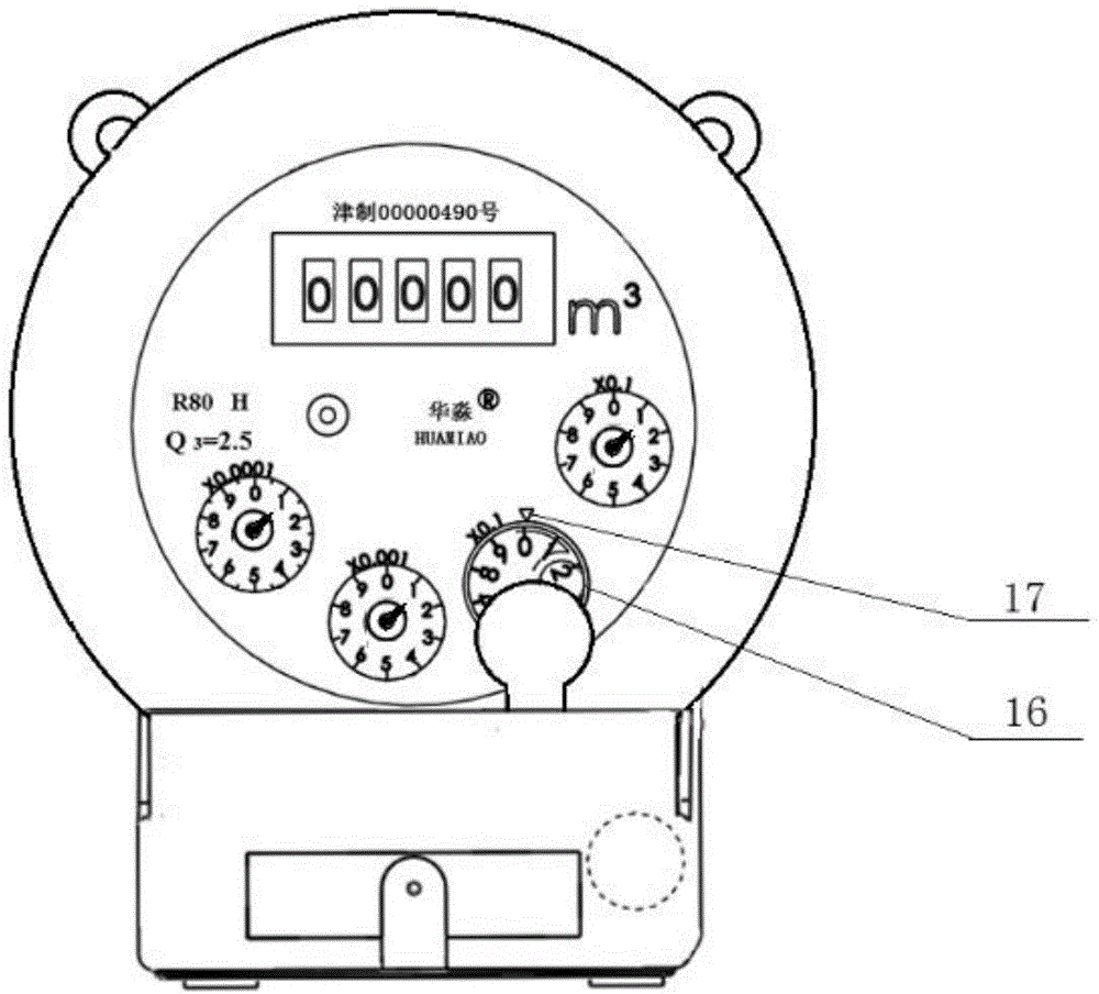
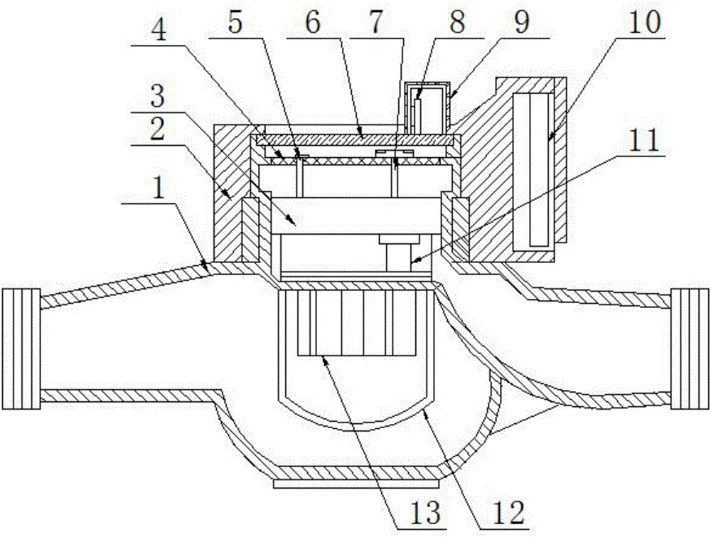
[0021] A mechanical remote transmission water meter with a new type of magnetic sensitive counting structure, which is composed of a rotor-type water meter and a control unit. It is mainly composed of impeller box 13, impeller, and impeller shaft 11. The indicating mechanism is mainly composed of dial 4, counting shaft group and transmission gear group 3. The control unit is mainly composed of shell 2, sensor mechanism 9 and control module 10.

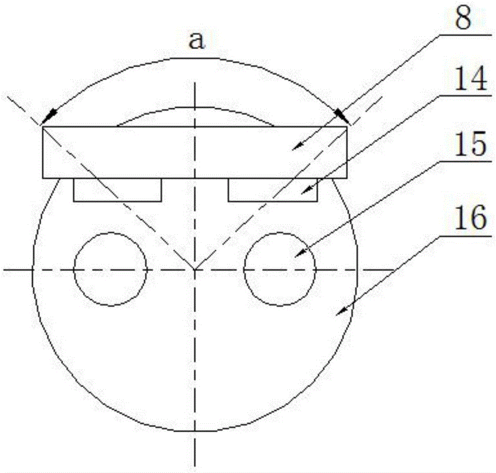
[0022] The counting axis group includes an induction counting axis 7 equipped with a magnet and three to five pointer counting axes 5 equipped with pointers. Two magnets 15 are installed on the induction counting axis, and a sensor mechanism is installed outside the watch glass. The sensor me...


PUM


Abstract

The invention relates to a mechanical remote water meter provided with a novel magnetic sensing counting structure. The mechanical remote water meter is formed by a rotating vane type water meter and a control unit, wherein a metering mechanism of the rotating vane type water meter is mainly formed by an impeller box, an impeller and an impeller shaft; a counting shaft of an indicating mechanism comprises an induction counting shaft provided with two magnets and three to five pointer counting shafts provided with pointers; a sensor mechanism is arranged outside watch glass; a PCB (Printed Circuit Board) of a sensor mechanism is arranged in a magnetic shielding case; the PCB is vertically installed; two magneto-dependent sensors are vertically fixed on the PCB; a vertical surface where the PCB is located and the position of a middle point of a connecting line of the two magnets are eccentric; a vertical surface where the two magneto-dependent sensors are located is parallel to any diameter of the circumference formed by the two magnets; and the distances between the two magneto-dependent sensors and the center of the connecting line of the two magnets are the same. Through adoption of the non-contact magnetic sensing counting mechanism, the precise counting can be realized, and the shielding of a dial can be reduced to the greatest extent, and the mechanical remote water meter is easily installed and observed.

Description

technical field [0001] The invention belongs to the field of water meters, in particular to a mechanical remote water meter with a novel magnetic-sensitive counting structure. Background technique [0002] Most of the existing automatic counting water meters are photoelectric direct-reading water meters. It can read the value of the water meter through the internal photoelectric system, so as to realize the remote reading. However, there are many problems in the existing photoelectric direct-reading water meter. First of all, its electronic control system must be integrated inside the water meter, which is difficult to process. Once water enters during use, it will cause damage to the circuit board. Moreover, the existence of factors such as light and air bubbles will affect the accuracy and reliability of the photoelectric reading of the electronic control system. [0003] At present, there are also magnetic induction mechanical remote water meters. It achieves ele...

Claims


Application Information

Patent Timeline
IPC IPC(8): G01F1/56G01F1/28G01F15/06G01F15/07
CPCG01F1/28G01F1/56G01F15/066G01F15/07
Inventor 张炳华
Owner TIANJIN BINGHUA ENERGY TECH
Why Eureka
Try Eureka