
Method for adjusting combustion of W flame furnace by changing quantity of oil secondary air

A secondary air volume, flame furnace technology, applied in the combustion method, adjusting the air supply, controlling the combustion and other directions, can solve the problem of high content of combustibles in fly ash, reduce the content of combustibles in fly ash, increase the stroke, and facilitate burnout Effect

Active Publication Date: 2009-09-30
HARBIN INST OF TECH
View PDF0 Cites 12 Cited by
  • Summary
  • Abstract
  • Description
  • Claims
  • Application Information

AI Technical Summary

Problems solved by technology

[0003] The purpose of the present invention is to solve the problem that the content of fly ash combustibles is too high during the use of the flame combustion technology of the existing W-type flame boiler designed by Foster Wheeler Company, and to provide a method to adjust the oil secondary air volume by changing W flame furnace combustion method

Method used


Image

  • Method for adjusting combustion of W flame furnace by changing quantity of oil secondary air
  • Method for adjusting combustion of W flame furnace by changing quantity of oil secondary air
  • Method for adjusting combustion of W flame furnace by changing quantity of oil secondary air

Examples


specific Embodiment approach 1

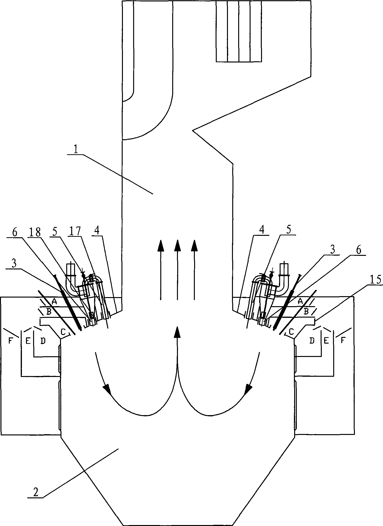
[0007] Specific implementation mode one: combine figure 1 Describe this embodiment, this embodiment is realized by the following method: when oil gun 3 ignites boiler normal operation, open damper 9 in the 3rd wind layer C, feed oil secondary air continuously, the oil that passes into The secondary air volume is 12% to 40% of the secondary air volume, and the opening of the damper 9 is between 20% and 100%. The opening degree of the damper 9 can ensure that the oil secondary air continuously passes into the combustion chamber between 20-100%.

[0008] Because the oil secondary air passed into the combustion chamber 2 is on the leeward side, the introduction of the oil secondary air will not affect the combustion situation in the burnout chamber 1 . After the oil secondary air with higher wind speed is introduced (the wind speed is higher than the concentrated coal powder flow), the upward momentum of the arch is increased, and the primary air powder can be driven downward, pr...

specific Embodiment approach 2

[0009] Specific implementation mode two: combination figure 1 Describe this embodiment, when the calorific value of coal in this embodiment is above 24 megajoules, the opening degree of damper 9 is 100%, and the secondary air volume of the oil that passes through is 40% of the secondary air volume. When the calorific value of the coal quality is above 24 MJ, the calorific value of the coal quality is very high, the amount of coal supply is very small, and the primary air volume is very small, resulting in a serious shortage of oxygen supply, and a large damper needs to be opened9. Other methods are the same as in the first embodiment.

specific Embodiment approach 3

[0010] Specific implementation mode three: combination figure 1 Describe the present embodiment, when the coal calorific value of the present embodiment is 22-24 megajoules, the opening degree of the damper 9 is 80%-100%, and the secondary air volume of the oil introduced is 37%-40% of the secondary air volume. %. When the calorific value of coal is 22-24 megajoules, the calorific value of coal is higher, the amount of coal feed is less, and the primary air volume is small, resulting in a serious shortage of oxygen supply, and a large damper 9 needs to be opened. Other methods are the same as in the first embodiment.


PUM


Abstract

The invention discloses a method for adjusting combustion of a W flame furnace by changing quantity of oil secondary air, relates to a method for combustion of a W flame furnace, and solves the problem that the fly ash combustible content is over high when the flame combustion technology of the prior W flame furnace designed by Foster Wheeler Company is used. The method is realized by the following steps: when a boiler works normally after an oil gun (3) ignites, opening an air door (9) in a third air layer (C), and continually introducing oil secondary air, wherein the quantity of the introduced oil secondary air is 12 to 40 percent of the quantity of secondary air; and the opening degree of the air door (9) is between 20 and 100 percent. By opening the air door (9) in the third air layer (C) and continually introducing the oil secondary air into a combustion chamber, the combustion condition in the combustion chamber is changed so that a ratio of an upper arch momentum to a lower arch momentum is 6:1-9:1, thereby increasing coal dust stroke and prolonging the detention time of coal dust. The method is favorable for burnout and can effectively reduce the fly ash combustible content.

Description

technical field [0001] The invention relates to a method for burning in a W flame furnace. Background technique [0002] The existing W-shaped flame boiler designed by Foster Wheeler Company in the United States has a high combustible content in the fly ash during use. The combustion chamber of the W flame boiler is divided into an upper burnout chamber 1 and a lower combustion chamber 2, the front wall and the rear wall between the burnout chamber 1 and the combustion chamber 2 are furnace arches 4, and each furnace arch 4 A number of double-cyclone pulverized coal separation burners are arranged on the top, and the pulverized coal airflow sprayed downward stretches downward after being ignited at a speed of 15-25m / s, and turns upward after meeting the secondary air at the lower part of the combustion chamber 2. Rising along the central axis of the inner cavity of the combustion chamber 2, a W-shaped flame is formed, and the gas flow of combustion products rises into the b...

Claims


Application Information

Patent Timeline
Patent Type & Authority Applications(China)
IPC IPC(8): F23N3/00F23C7/02
Inventor 李争起任枫王琳陈智超张福成
Owner HARBIN INST OF TECH
Learn More