
Touch control panel device

A touch panel and plane technology, applied in the direction of instruments, electrical digital data processing, input/output process of data processing, etc., can solve the problems of inconvenience, interference contact point detection, low production yield, etc.

Inactive Publication Date: 2009-09-30
ELAN MICROELECTRONICS CORPORATION
View PDF0 Cites 25 Cited by
  • Summary
  • Abstract
  • Description
  • Claims
  • Application Information

AI Technical Summary

Problems solved by technology

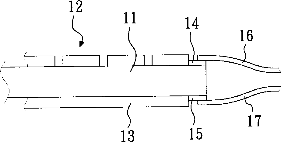
When the first and second extension line units 16 and 17 extend to the outside of the substrate 11, the gap between the first and second extension line units 16 and 17 often causes the first and second extension line units 16 to , 17 forms noise and interferes with the detection of contact points, resulting in a problem of low production yield
[0005] It can be seen that the above-mentioned existing capacitive touch panel device obviously still has inconveniences and defects in structure and use, and it is necessary to provide a touch panel device with simple structure, simplified manufacture and can improve the above problems
In order to solve the above-mentioned problems, the relevant manufacturers have tried their best to find a solution, but no suitable design has been developed for a long time, and there is no suitable structure for general devices and products to solve the above-mentioned problems. This is obvious. It is a problem that relevant industry players are eager to solve

Method used


Image

  • Touch control panel device
  • Touch control panel device
  • Touch control panel device

Examples


Embodiment Construction

[0060] In order to further explain the technical means and effects adopted by the present invention to achieve the intended invention purpose; below in conjunction with the accompanying drawings and preferred embodiments, the specific implementation, structure, features and effects of the touch panel device proposed according to the present invention , as detailed below.

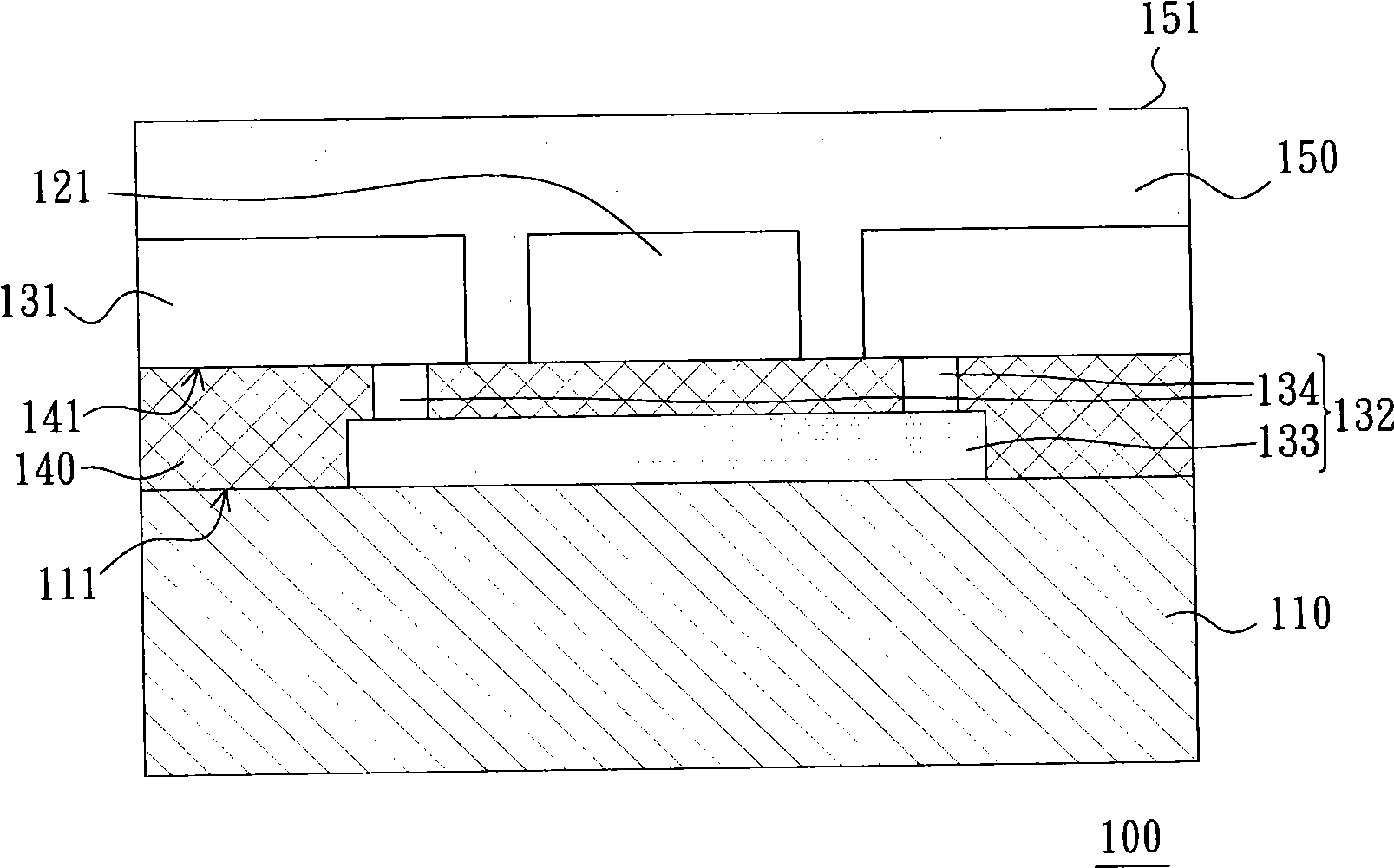
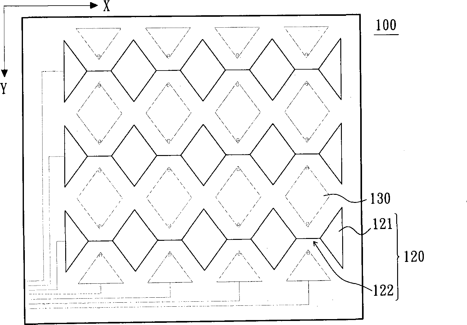
[0061] refer to figure 2 and image 3 The first embodiment of the technical solution provides a touch panel device 100 , which includes a substrate layer 110 , at least one first electrode group 120 , at least one second electrode group 130 , an insulating layer 140 and a scratch-resistant layer 150 . In this embodiment, the touch panel device 100 includes a plurality of first electrode groups 120 and a plurality of second electrode groups 130 , and the first electrode groups 120 and the second electrode groups 130 are disposed on the same side of the substrate layer 110 . The insulating layer 140 is form...


PUM


Abstract

The invention relates to a touch control panel device, which comprises a substrate layer, an insulating layer and a plurality of first and second electrode groups. The insulating layer is formed on the surface of the substrate layer; each first electrode group comprises a plurality of first electrode plates and a plurality of first conducting wires which are electrically connected with the adjacent first electrode plates; and each second electrode group comprises a plurality of second electrode plates and a bridging conducting wire which is electrically connected with the adjacent second electrode plates. The first electrode groups and the second electrode plates in the second electrode groups are mutually and alternately formed on the surface of the insulating layer, and the bridging conducting wire is formed on the surface where the substrate layer and the insulating layer are connected. The device has the advantages that the device has simple structure and easy manufacture, and can reduce the electromagnetic interference from the outside.

Description

technical field [0001] The present invention relates to a touch panel device, in particular to a capacitive touch panel device. Background technique [0002] In general life, touch panels are widely used in various electronic products, for example, cash machines of financial institutions, navigation information systems of department stores, or personal digital assistants (Personal Digital Assistant, PDA). ) and notebook computers. According to different detection principles, different types of touch panels have different advantages and disadvantages. [0003] figure 1 The above is the structure of the current general capacitive touch panel device. This capacitive touch panel device has a flat substrate 11, the first electrode unit 12 formed on the top surface of the substrate 11, and the first electrode unit 12 formed on the bottom surface of the substrate 11. Two electrode units 13 extend inward from the periphery of the top surface of the substrate 11 and electrically c...

Claims


Application Information

Patent Timeline
IPC IPC(8): G06F3/044
Inventor 叶仪晧邓智先
Owner ELAN MICROELECTRONICS CORPORATION
Learn More