Digital voice transmission system based on LAN

A digital voice and transmission system technology, applied in time division multiplexing system, data exchange through path configuration, telephone communication, etc., can solve the problems of unsatisfactory continuity and delay characteristics, large delay, etc., and reduce construction and maintenance costs, avoiding congestion and blocking, and convenient wiring and layout

Active Publication Date: 2009-09-30
BEIJING PHILISENSE TECH
View PDF0 Cites 27 Cited by
  • Summary
  • Abstract
  • Description
  • Claims
  • Application Information

AI Technical Summary

Problems solved by technology

However, adopting such a deep buffer scheme will cause audio delay, and the length of the delay depends on the size of the preset buffer area for deep storage. The larger the buffer area, the better the continuity of audio data, but the delay is also larger, so this solution cannot meet the requirements of strict continuity and delay characteristics of the application (such as the application of real-time voice transmission)

Method used


Image

  • Digital voice transmission system based on LAN
  • Digital voice transmission system based on LAN
  • Digital voice transmission system based on LAN

Examples


Embodiment Construction

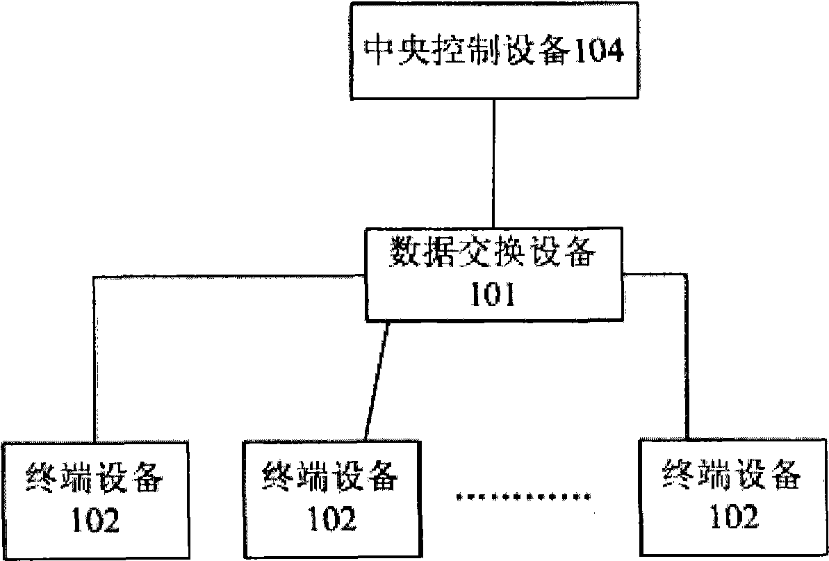
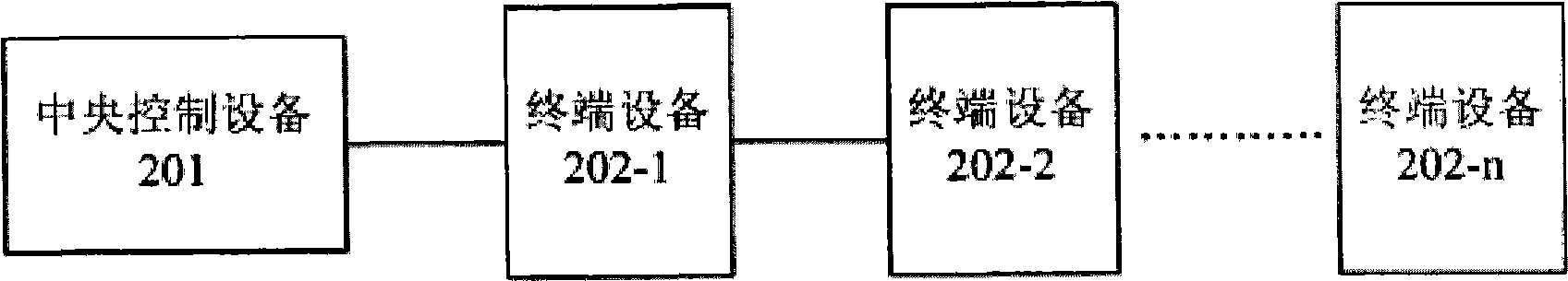
[0020] figure 2 shows the structure diagram of the system for digital voice transmission according to the present invention. Different from the traditional star LAN topology, the system for digital voice transmission according to the present invention adopts a serial cascade connection mode. Specifically, in this serial cascade system, the uplink port 402 of each terminal device 202 is connected to the downlink port 404 of its previous stage terminal device, and the downlink port 404 of each terminal device is connected to the uplink port 404 of the subsequent stage terminal device. 402 connection, and so on, the uplink port 402 of a front-end terminal device 202 is connected to the hardware interface 304 of the central control device 201 . The audio signal sequences from each of the terminal devices are serially transmitted upstream to the central control device 201, and the audio signals from the central control device 201 are serially transmitted downstream to at least one...


PUM


Abstract

A digital voice transmission system based on LAN comprises multiple terminal equipment (202-1, 202-2, to 202-n) and central control equipment (201) characterized in that multiple terminal equipment (202-1, 202-2, to 202-n) are serially connected and the central control equipment (201) is connected with a terminal equipment (202-1) of most significant end in the serially connected equipments; audio frequency signal from each terminal equipment are serially transmitted uplink to the central control equipment and audio frequency signal from the central control equipment are serially transmitted downlink to at least one of the multiple terminal equipment.

Description

technical field [0001] The present invention relates to the technical field of digital signal communication, in particular to a digital voice transmission method and system based on a local area network. Background technique [0002] figure 1 shows a common topological structure of a traditional star-shaped local area network based on an Ethernet transmission protocol, in which a data exchange device 101 is used between multiple terminal devices 102 to realize the exchange of data packets based on various protocols, According to the Ethernet transmission protocol, since the transmission cable between each terminal device 102 and the data exchange device 101 has a maximum transmission distance of about 100 meters at a data rate of 100 Mbps, this topology is more suitable for terminals such as Internet cafes and offices The occasions where the equipment is concentrated and each terminal equipment is used independently. [0003] Using the traditional star LAN topology for dig...

Claims


Application Information

Patent Timeline
Patent Type & Authority Applications(China)
IPC IPC(8): H04M7/00H04L12/28H04J3/06
Inventor 杨振华曹忻军施亮金日吾
Owner BEIJING PHILISENSE TECH
Why Eureka
Try Eureka