Control method and device based on an automobile line control brake system

A control method and technology of automobile lines, applied in the direction of brake transmission, brakes, vehicle parts, etc., can solve the problems of easy braking, low safety, complex structure, etc., and achieve short braking time, small quality and volume. , the effect of short braking distance

Inactive Publication Date: 2009-10-07
CHERY AUTOMOBILE CO LTD
View PDF1 Cites 13 Cited by
  • Summary
  • Abstract
  • Description
  • Claims
  • Application Information

AI Technical Summary

Problems solved by technology

But its disadvantage is that it adopts the traditional mechanical structure, which is complicated in structure, low in efficiency, easy to cause braking, and low in safety.

Method used


Image

  • Control method and device based on an automobile line control brake system

Examples


Embodiment Construction

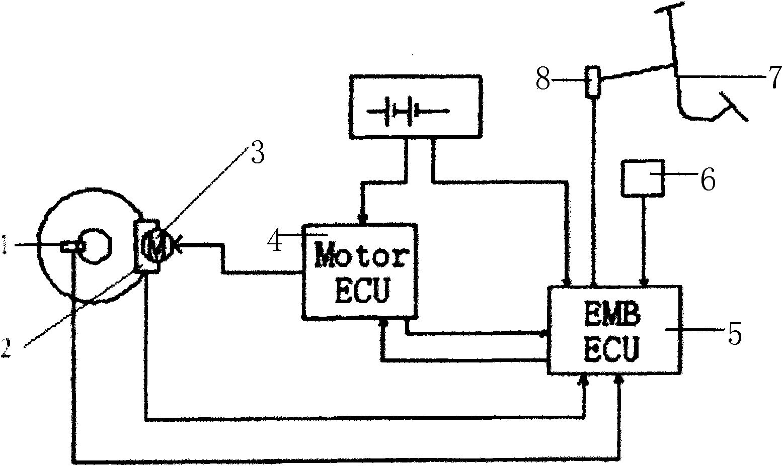
[0017] As shown in the figure, the signal output terminal of the electric brake main control unit 5 is connected to the signal input terminal of the brake control unit 4 , and the signal output terminal of the brake control unit 4 is connected to the brake 3 . The pedal upstroke sensor and the pressure sensor group 8 are connected to the signal input end of the main control unit 5 of the electric brake. The wheel speed sensor 1 and the braking force sensor 2 are respectively connected to the signal input terminals of the electric brake main control unit 5 .

[0018] The electric brake master control unit 5 receives the brake state signal, and according to the brake state signal, the electric brake master control unit sends a control signal to the brake control unit, and the brake control unit 4 obtains The required braking force of each wheel sends an instruction to make the motor in the electric brake 3 act.

[0019] The braking state signal received by the electric brake ma...


PUM


Abstract

Control method and device based on an automobile line control brake system, with features of simple structure, short brake reaction time and high reliability. The control method based on an automobile line control brake system is characterized in that: an electric brake main control unit receives the brake state signals and sends the control signals to a brake control unit based on the brake state signals and the brake control unit obtains the required brake force of each vehicle wheel based on the signals sent from the electric brake main control unit and the command is sent to make the motor in the electric brake operate.

Description

technical field [0001] The invention relates to a control method and device based on an automobile by-wire brake system. Background technique [0002] At present, the prior art most relevant to the present invention is: automobile brake control device (CN200620158837.X), its main structure is that the solenoid valve is installed at the brake fluid output port of the brake master cylinder, and the wheel brake cylinder The hydraulic oil pipe is connected to the solenoid valve, and the control circuit of the solenoid valve is also connected with the engine tachometer and the speedometer. Through this technology, it can be realized that when the car is completely stopped, no matter whether the engine is turned off or not, as long as the speed drops to zero kilometers, the solenoid valve will automatically start to perform braking, which can replace the performance of the hand brake. However, its disadvantage is that it adopts the traditional mechanical structure, which is compl...

Claims


Application Information

Patent Timeline
Patent Type & Authority Applications(China)
IPC IPC(8): B60T8/172B60T8/32B60T13/74
Inventor 姜竹胜张亮
Owner CHERY AUTOMOBILE CO LTD
Why Eureka
Try Eureka