Optical device and camera device

A technology for optical devices and optical components, applied in the directions of optics, optical components, installation, etc., can solve the problems of increasing the number of components, increasing the manufacturing cost of lens barrels, etc., and achieve the effect of preventing movement

Inactive Publication Date: 2009-10-07
TAMRON
View PDF1 Cites 3 Cited by
  • Summary
  • Abstract
  • Description
  • Claims
  • Application Information

AI Technical Summary

Problems solved by technology

[0007] However, in the prior art described in the above-mentioned Patent Document 1, since it is necessary to add an active part for the interlocking key to act on the side of the mating surface between the lens frame and the interlocking key, there is an increase in the number of parts and the manufacturing cost of the lens barrel. additional questions

Method used


Image

  • Optical device and camera device
  • Optical device and camera device
  • Optical device and camera device

Examples


Embodiment Construction

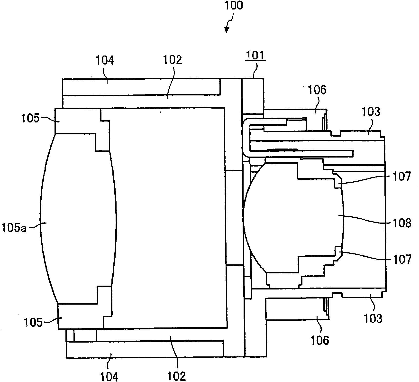
[0033] Preferred embodiments of the optical device and the imaging device of the present invention will be described in detail below with reference to the drawings. In this embodiment, as an example of the optical device according to the embodiment of the present invention, an application example applied to a lens device mounted on an imaging device is shown.

[0034] First, a lens device according to an embodiment of the present invention will be described. figure 1 It is an explanatory diagram showing a lens device according to an embodiment of the present invention. exist figure 1 In , a cross section of the lens device according to the embodiment of the present invention is shown on a plane passing through the optical axis. exist figure 1 Among them, the lens device 100 according to the embodiment of the present invention includes a lens barrel body 101 having a substantially cylindrical shape.

[0035] The lens barrel body 101 is composed of a main lens barrel 102 and...


PUM


Abstract

The present invention provides an optical device and a camera device, wherein a lens unit is provided with a ganged plate (204), having a ganged key (203) extending in an optical axis direction and rotating gangedly along with a rotation of a zooming loop; a rear element lens frame (107), having a helical part (201) on an external circumference surface containing an arris extending in a direction inclined relative to the optical axis direction, and a key groove (202) jointed with the ganged key (203) rotating along with the rotation of the ganged plate (204); and a back lens cone, arranged on an external side of the rear element lens frame (107) and showing a approximate cylinder shape, and having helical parts for forming a helical mechanism by conjoining with the helical part (201) on an inner circumference surface, so as to support the rear element lens frame (107), the ganged key (203) and the key groove (202) movably in the optical axis direction through the helical mechanism, inclined in a direction different from the helical part (201) relative to the optical axis direction. Thereby, by means of a simple structure, it is capable of preventing the position of the optical component from departure caused by a clearance between the helical part and the helical support part, and the mobile performance of the optical component will not be reduced.

Description

technical field [0001] The present invention relates to an optical device that uses a screw mechanism to move an optical member in an optical axis direction, and an imaging device including the optical device. Background technique [0002] Conventionally, there is a lens barrel in which the lens frame is displaced along the edge of the spiral portion by engaging the outer peripheral surface of the lens frame provided in the lens barrel with the inner peripheral surface of the lens barrel, thereby displacing the lens frame. Move the lens frame in the direction of the optical axis. There is a technique in which, in such a lens barrel, an interlocking key rotatable about the optical axis is engaged with a key groove provided on the outer periphery of the lens frame, and the lens frame is rotated as the interlocking plate rotates. [0003] In such a technique, when a gap (gutter, gutter) occurs between the helical parts provided on the outer peripheral surface of the lens frame...

Claims


Application Information

Patent Timeline
IPC IPC(8): G02B7/04H04N5/225
Inventor 高桥康秀
Owner TAMRON
Why Eureka
Try Eureka