Design method of anti-blockage runner structures of douches of labyrinth runner structure

A technology of labyrinth flow channels and emitters, which is applied in the direction of instruments, calculations, and special data processing applications, etc., and can solve problems such as non-blocking design methods of emitters and reduction of hydraulic performance of emitters

Inactive Publication Date: 2009-10-07
NORTHWEST A & F UNIV
View PDF2 Cites 15 Cited by
  • Summary
  • Abstract
  • Description
  • Claims
  • Application Information

AI Technical Summary

Problems solved by technology

For this reason, relevant scholars in my country have proposed a flow channel design method to eliminate the vortex area in the flow channel and an emitter with an arc-shaped flow channel structure. These methods not only improve the anti-clogging ability of the emitter, but also reduce the hydraulic power of the emitter to a certain extent. Performance, not the most scientific anti-clogging design method for emitters

Method used


Image

  • Design method of anti-blockage runner structures of douches of labyrinth runner structure
  • Design method of anti-blockage runner structures of douches of labyrinth runner structure
  • Design method of anti-blockage runner structures of douches of labyrinth runner structure

Examples


Embodiment Construction

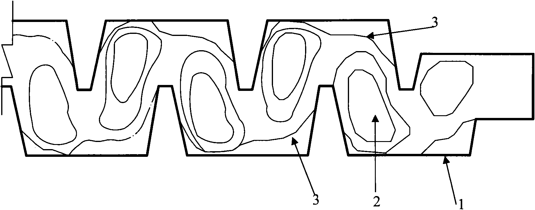
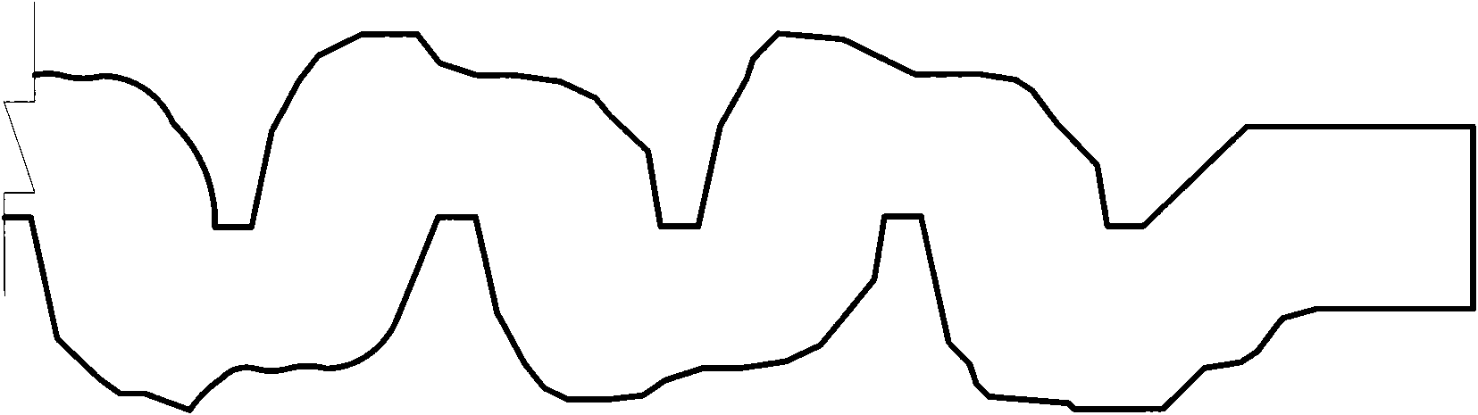
[0030] Referring to the accompanying drawings, the anti-clogging flow channel structure design method of the labyrinth flow channel structure sprinkler of the present invention includes the drawing of the initial flow channel structure form, the numerical simulation of the two-phase flow and the drawing of the contour map of the sand content, the flow channel boundary line There are five parts including redesign, finalization of runner structure and standardized design of runner boundary line. The specific design method is:

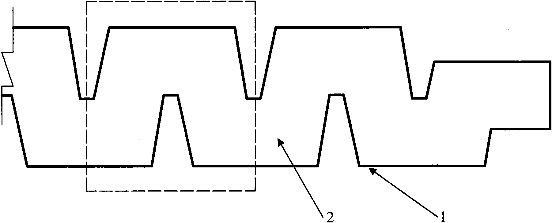
[0031] The first step is to design the initial structure of the emitter structure according to the pattern of the labyrinth structure of the conventional emitter. figure 1 as shown, figure 1 The part in the dotted line box is called a flow channel unit of the emitter structure, including the flow channel boundary line 1 and the flow channel 2. The entire emitter flow channel structure is formed by copying and translating multiple flow channel units.

[0...


PUM


Abstract

The invention discloses a design method of anti-blockage channel structures of douches of a labyrinth channel structure, which includes five parts of: the drawing of the shape of an original runner structure, drawing of a contour map of sediment concentration with two-phase numerical simulation, redesigning of a boundary line of the runner, sizing of the shape of the runner structure, standardized designing of the boundary line of the runner, etc. The method optimizes parameters of the runner structure of the douche. Compared with the douche in the shape of the original runner structure, in the designed douche, the sediment concentration distribution in the runner is more uniform, thus basically eliminating the phenomenon that a great number of solid particles accumulate at the runner wall. Therefore, the anti-blockage capability of the douche is doubled and the service life reaches twice that of the original service life. The hydraulic performance and prototype of the designed douche remain unchanged and the manufacture technique and material usage of the products are the very same with that of present products.

Description

technical field [0001] The invention relates to a design method of a drip irrigation emitter frequently used in agricultural irrigation, in particular to a design method of an anti-clogging flow path structure of an emitter with a labyrinth flow path structure. Background technique [0002] The drip irrigation emitter is the core component of the drip irrigation system. The hydraulic performance and anti-clogging ability of the emitter directly determine the irrigation quality and system life of the drip irrigation project. Therefore, the rational design of the drip irrigation emitter and the improvement of its anti-clogging ability and hydraulic performance are very important for improving the drip irrigation system. It is of great significance to improve the performance, improve the service life of the system and reduce the cost of the system. At present, the flow channel structure of drip irrigation emitters often adopts a labyrinth structure. The hydraulic performance an...

Claims


Application Information

Patent Timeline
Patent Type & Authority Applications(China)
IPC IPC(8): G06F17/50
Inventor 牛文全吴普特喻黎明范兴科
Owner NORTHWEST A & F UNIV
Why Eureka
Try Eureka