Jet tee joint

A jet and tee technology, applied in the field of jet tee, can solve the problems of complicated installation, use, maintenance, long running time, lack of operation and maintenance skills, etc. handy effect

Inactive Publication Date: 2013-07-17
JIANGSU UNIV
View PDF10 Cites 9 Cited by
  • Summary
  • Abstract
  • Description
  • Claims
  • Application Information

AI Technical Summary

Problems solved by technology

The cost of electronic pulse devices, pulse solenoid valves and other devices is relatively high, and the installation, use, and maintenance are relatively complicated. They often require electronics-related professionals to operate and maintain them. However, most users of micro-irrigation systems are local farmers, who lack corresponding operations, Maintenance skills; micro-irrigation systems generally run for a long time, and elastic materials such as rubber, plastic films, and springs are prone to fatigue and even damage during long-term, high-frequency frequent reciprocating operations; the pulse frequency depends on the stiffness and initial The amount of compression, long-term operation will lead to changes in the stiffness and elastic modulus of the elastic material, the elasticity will decrease, and the sensitivity and reliability will decrease to varying degrees, which will affect the long-term operation and use of the pulse micro-irrigation system; the use of elastic materials will inevitably increase The complex structure of the pulse generator puts forward higher requirements for mechanical sealing, manufacturing precision, reliability and durability

Method used


Image

  • Jet tee joint
  • Jet tee joint
  • Jet tee joint

Examples


Embodiment 1

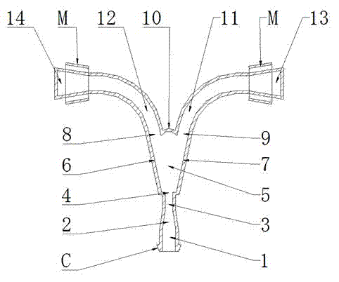
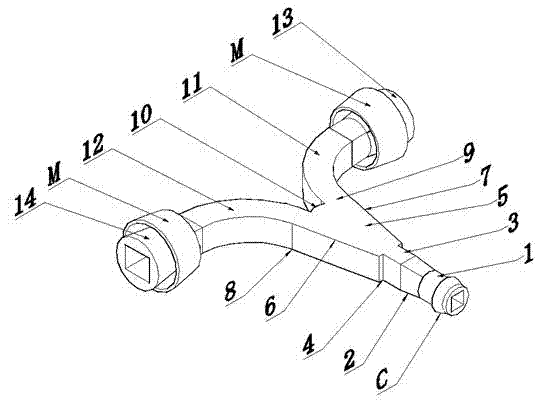
[0023] Embodiment 1: refer to figure 1 , figure 2 and image 3 , The jet tee is composed of an inlet section 1, a jet element F, an outlet section I14 and an outlet section II13.

[0024] refer to figure 1 and figure 2 , the jet element F includes a constriction section 2, a diversion section 3, a nozzle 4, a jet space 5, a side wall I6, a side wall II7, an output port I8, an output port II9, a splitter 10, an output channel I12, and an output channel II11; The front end of the element F is a contraction section 2 with a large front and a small rear shape. The front end of the contraction section 2 is connected to the end of the water inlet section 1, and the end of the contraction section 2 is connected to the front end of the diversion section 3. The end of the diversion section 3 is a nozzle 4. Behind the nozzle 4 is a jet space 5 with a small front and a large rear. The two sides of the jet space 5 are side wall I6 and side wall II7 respectively; It is divided into ...

Embodiment 2

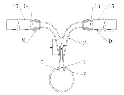
[0031] Embodiment 2: refer to Figure 5 , Figure 6 and Figure 7 . For a jet tee shown in Example 2, the angle between the central axis of the nozzle 4 and the central axis of the outlet section I14 is 12°, the angle between the central axis of the nozzle 4 and the central axis of the outlet section II13 is 12°, and the capillary I16 It is distributed on one side of branch Z with capillary II15. The structural features of the rest of the components are the same as those in Embodiment 1, and the parts with the same structure are denoted by the same reference numerals, and will not be described again. The principle and implementation process of this embodiment are also the same as those of the first embodiment, so the description thereof is omitted.


PUM


Abstract

The invention discloses a jet tee joint for micro-irrigation. The jet tee joint comprises an inlet section, a jet element and two outlet sections. When the jet tee joint is applied to a micro-irrigation system, the inlet section is connected with a branch tube, the jet element is positioned between the inlet section and the outlet sections, each of the two outlet sections is connected with a capillary tube, water flow passes the inlet section via the branch tube to enter the jet element so as to generate jet wall attachment effect, and under the feedback effect of water pressure load in the capillary tubes, wall-attached water flow generates intermittent deflection to enable the water flow to flow in the two capillary tubes alternately according to certain frequency, pulse water flow is formed in the capillary tubes and then enters an irrigation emitter, and strong turbulent and impacting water flow is formed in the irrigation emitter so as to improve anti-clogging capacity and irrigation uniformity of the irrigation emitter. The jet tee joint has the advantages of simple structure, reliability and high durability, can be formed by one-step injection molding, and is simple in machining process, low in manufacturing cost, convenient to mount and use, and applicable to various micro-irrigation systems for field crops, vegetables, forestry and fruit industry and the like.

Description

technical field [0001] The invention belongs to the technical field of agricultural water-saving irrigation, and relates to a capillary connection tee for a micro-irrigation system, in particular to a jet tee. Background technique [0002] Pulse micro-irrigation has the characteristics of strong anti-clogging performance and high uniformity of irrigation, and has been widely concerned and applied by countries all over the world. The pulse generator is the core device that turns the pressure water flow in the micro-irrigation system into a pulse water flow. The existing pulse generator generally generates pulse water flow through electronic pulse devices, pulse solenoid valves or elastic materials such as rubber, plastic films, and springs. The cost of electronic pulse devices, pulse solenoid valves and other devices is relatively high, and the installation, use, and maintenance are relatively complicated. They often require electronics-related professionals to operate and...

Claims


Application Information

Patent Timeline
Patent Type & Authority Applications(China)
IPC IPC(8): B05B1/08A01G25/02
Inventor 王新坤
Owner JIANGSU UNIV
Why Eureka
Try Eureka