
System and method for generating treatment patterns

A pattern and sub-pattern technology used in retinal photocoagulation

Inactive Publication Date: 2009-10-07
OPTIMEDICA CORP
View PDF1 Cites 15 Cited by
  • Summary
  • Abstract
  • Description
  • Claims
  • Application Information

AI Technical Summary

Problems solved by technology

However, the rapid transport of multiple beam spots in a pattern creates new problems

Method used


Image

  • System and method for generating treatment patterns
  • System and method for generating treatment patterns
  • System and method for generating treatment patterns

Examples


Embodiment Construction

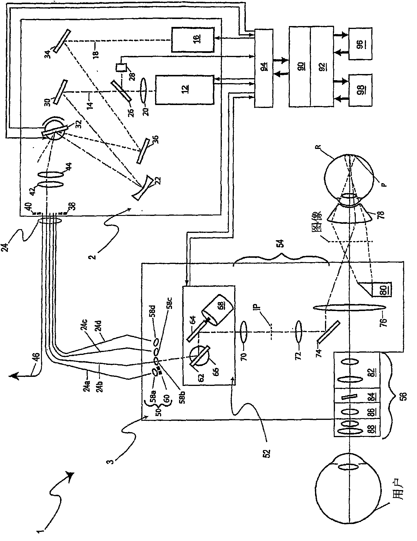
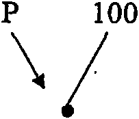
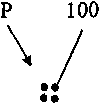
[0028] [0028] The present invention is a system and method for generating a pattern P of directed and manipulated light on a target ocular tissue (eg, retina) of a patient's eye. figure 1 An ophthalmic slit lamp based scanning photocoagulator 1 is described, which is a non-limiting example of a photocoagulation system for generating and projecting an alignment pattern of spots and / or processing a pattern of spots onto the retina R of a patient. The system 1 includes a light source assembly 2 and a slit lamp assembly 3 .

[0029] [0029] The light source assembly 2 includes a processing light source 12 and an alignment light source 16, the processing light source 12 is used to generate a beam 14 of processing light, and the alignment light source 16 is used to generate a beam 18 of alignment light. The treatment beam 14 from the treatment light source 12 is first conditioned by a lens 20 which is used in combination with a curved mirror 22 to prepare the treatment beam 14 for in...


PUM


Abstract

System and method for generating patterns P of aiming and treatment light on target eye tissue (e.g. the retina) of a patient's eye. The system includes light sources for treatment and aiming light, a scanner for generating patterns of spots of the generated light, a controller, and a graphic user interface that allows the user to select one of several possible spot patterns, adjust the spot density and / or spot size, and apply patterns with fixed or varied density. The patterns can be formed of interlaced sub-patterns and / or scanned without adjacent spots being consecutively formed to reduce localized heating. Partially or fully enclosed exclusion zones within the patterns protect sensitive target tissue from exposure to the light.

Description

[0001] [0001] This application claims priority to the following two U.S. provisional applications, U.S. Provisional Application No. 60 / 718,762 filed September 19, 2005, and U.S. Provisional Application No. 60 / 758,169 filed January 10, 2006. application, the contents of both are incorporated herein by reference. technical field [0002] [0002] The present invention relates to retinal photocoagulation techniques, and more particularly to systems and methods for patterned optical ophthalmic treatment. Background technique [0003] [0003] Visible lasers are currently used to photocoagulate a variety of diseases such as diabetic retinopathy and age-related macular degeneration. Although this type of visible laser treatment stops the underlying disease from developing, it can also be problematic. For example, because the treatment requires prolonged exposure of the eye (typically on the order of 100 ms) to visible laser light, the heat generated may cause damage to the sensory la...

Claims


Application Information

Patent Timeline
Patent Type & Authority Applications(China)
IPC IPC(8): A61N5/067
CPCA61F2009/00897A61F9/00821A61F9/008A61B18/22A61F2009/00863A61B2018/20351
Inventor D·H·莫当特G·马塞利诺M·W·威尔特伯格J·亨德里克森K·贝尔D·E·安德森
Owner OPTIMEDICA CORP
Learn More