Testing and venting pipe annulus

An annular space and annular technology, which is applied in the field of testing and exhausting the annular space of pipes, can solve the problems of increasing cost, time-consuming, failure to test the integrity of the inner annular area, etc.

Active Publication Date: 2009-10-07
GE OIL & GAS UK LTD
View PDF0 Cites 8 Cited by
  • Summary
  • Abstract
  • Description
  • Claims
  • Application Information

AI Technical Summary

Problems solved by technology

If an error occurs during manufacture, or if the pipe layers are damaged during production, it is desirable to identify this before the flexible pipe body is put into service, although damage will be found in service and replacement will be time consuming and costly
Known techniques exist for testing the integrity of some layers of flexible pipe bodies, however these techniques have not been successful in testing the integrity of the inner annulus

Method used


Image

  • Testing and venting pipe annulus
  • Testing and venting pipe annulus
  • Testing and venting pipe annulus

Examples


Embodiment Construction

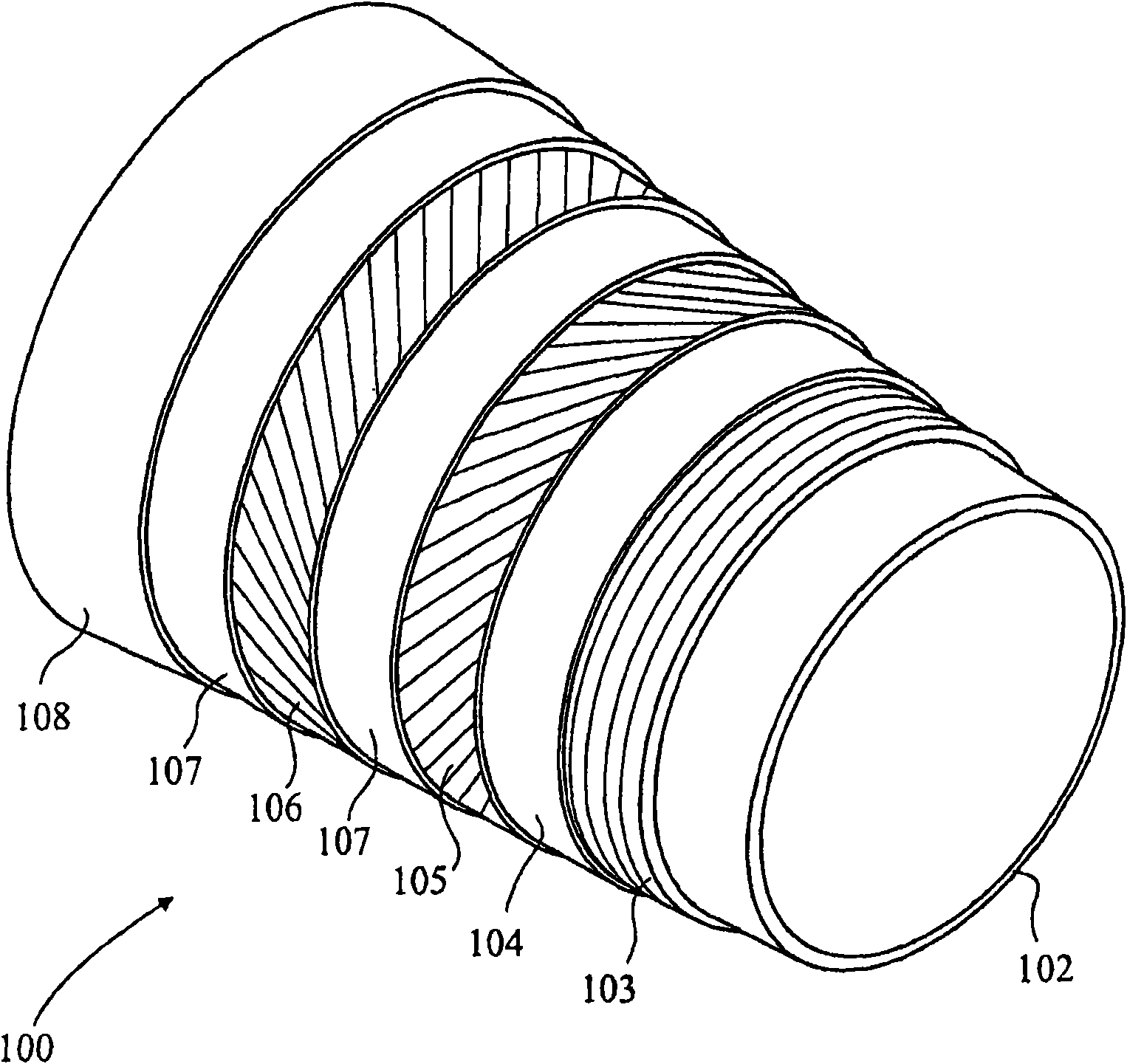
[0032] Throughout this specification reference will be made to flexible pipe. It should be understood that a flexible pipe is an assembly of a pipe body and one or more end fittings in which the ends of the pipe body are terminated. figure 1 It is shown how the pipe body 100 is formed from a composite of layered materials forming a pressure-containing conduit. although figure 1 A number of specific pipe layers are shown, but it should be understood that the invention is broadly applicable to composite pipe structures comprising two or more layers.

[0033] Such as figure 1 As shown in , the tubular body generally includes an innermost pressure sleeve 102 . Internal pressure sleeve 102 typically includes a polymer layer that ensures internal fluid integrity. It should be understood that the barrier layer itself may comprise many sub-layers. It should also be noted that it is preferred to refer to as figure 1 Embodiments of the present invention are utilized with the "smoo...


PUM


Abstract

A method and apparatus are disclosed for testing the integrity of a portion of flexible pipe body. The method includes the steps of, via at least one port in an end fitting assembly in which an end ofa portion of flexible pipe body is terminated, monitoring at least one parameter associated with an annulus region disposed between layers of the flexible pipe body, the annulus region being connected to the port by a connecting passageway.

Description

technical field [0001] The invention relates to a method and device for testing and venting flexible pipes. The present invention relates particularly, but not exclusively, to the testing and / or venting of the inner annulus of flexible risers and flowlines. Testing enables the integrity of the inner polymer layer to be verified, while venting prevents the accumulation of infiltration gases to reduce the risk of rupture. Background technique [0002] Flexible pipes are traditionally used to transport fluid products such as oil and / or gas and / or water from one location to another. Flexible pipe is especially useful for connecting subsea locations to sea level locations. Flexible pipe is generally formed as an assembly of a pipe body and one or more end fittings. The pipe body is generally formed as a composite of layered materials making up the pressure-containing piping. The tube structure tolerates large deflections without causing bending stresses that impair the tube's...

Claims


Application Information

Patent Timeline
IPC IPC(8): F16L23/00
CPCF16L23/006G01M3/283F16L2011/047F16L2101/30F16L11/12
Inventor T·埃克莱斯顿
Owner GE OIL & GAS UK LTD
Why Eureka
Try Eureka