
Method to automatically decode microarray images

A microarray and microarray chip technology, applied in image enhancement, image analysis, image data processing, etc., can solve the problems of non-common algorithms, uneven probe intensity and geometric structure, and unproposed correction of trapezoidal distortion in microarray images And other issues

Active Publication Date: 2009-10-07
KONINKLIJKE PHILIPS ELECTRONICS NV
View PDF0 Cites 2 Cited by
  • Summary
  • Abstract
  • Description
  • Claims
  • Application Information

AI Technical Summary

Problems solved by technology

Extracting data from microarray images has many inherent problems: inconsistent hybridization leads to uneven probe intensities and geometries; placement of the chip into the scanner is not fixed, meaning the corners of the chip can be anywhere ;scanners often distort the resulting images, which creates problems for converting these images into the required data; since there are many different design patterns at the same time, benchmarks can be placed in many different combinations
Brandle et al. [Ref. 1] and Uehara and Kakadiaris [Ref. 6] both present methods for all the functions needed to convert an image to the desired value, and both advocate the use of the Radon transform (see below), but as far as we know However, no method has been proposed for correcting the keystone problem in microarray images
The software tool BioDiscovery Imagene 7.0 claims to automatically find sites and place grids even in batch-mode processing for multiple arrays, however these algorithms are not currently publicly available (http: / / www / biodiscovery.com / index / imagene-cgh)

Method used


Image

  • Method to automatically decode microarray images
  • Method to automatically decode microarray images
  • Method to automatically decode microarray images

Examples


Embodiment Construction

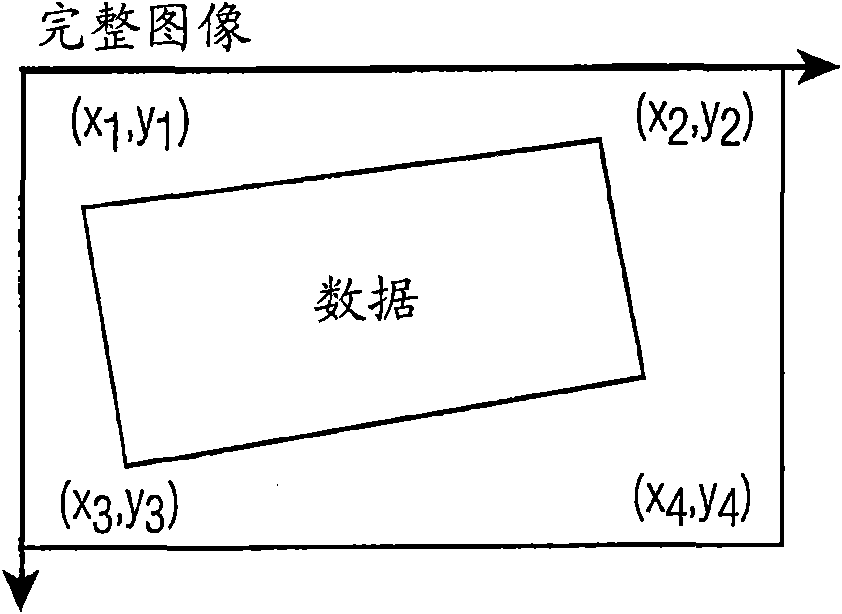
[0040] The disclosure herein presents an automated method for finding the corners of a microarray image and gridding or finding internal probes of a microarray image that facilitates decoding the image into numbers. We used image processing methods such as Radon transform and fast Fourier transform as well as several heuristic algorithms to find the microarray corners and precise positions of the probes. Based on our technique, we are able to identify corners to within a few pixels even in the layout of the corners themselves without probes.

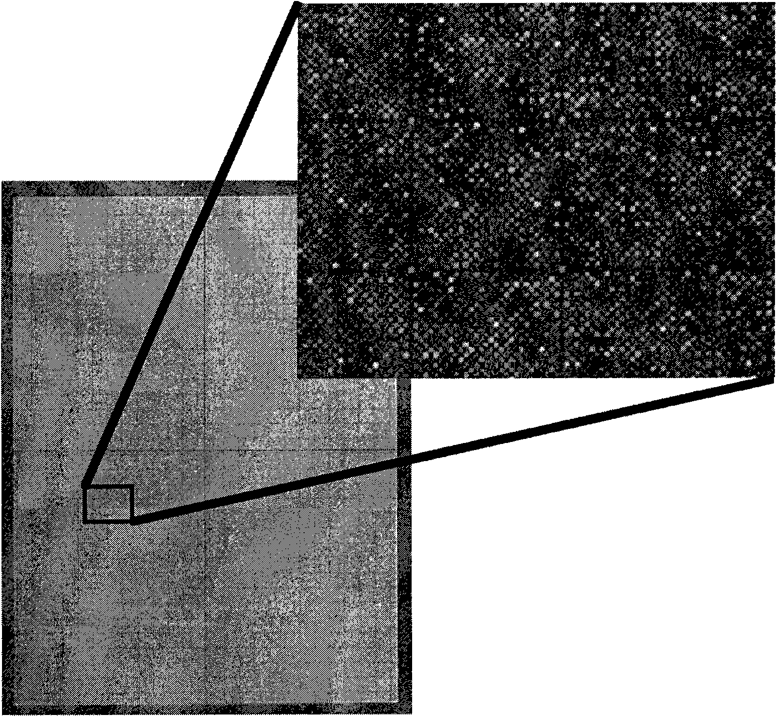
[0041] exist figure 1An example of a high-density microarray image (in our case a ROMA image) is shown in . There are a variety of probe design placement methods. The probes examined so far are squares with sides of 16 μm with 2 μm channels between them. These images may be scanned at 5 μm, 2 μm or 1 μm, or even sub-micron resolutions are contemplated, resulting in images with 3, 8 or 16 pixels per probe and 0, 1 or 2 pixels per chann...


PUM


Abstract

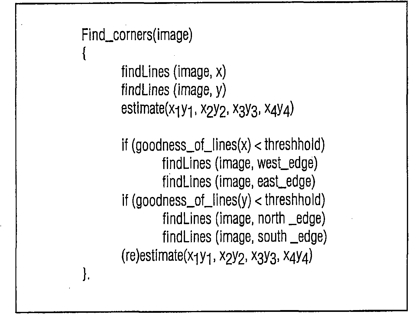
A method of automatically identifying the microarray chip corners and probes, even if there are no probes at the corners, in a high density and high resolution microarray 5 scanned image having an image space, wherein the method minimizes the error distortions in the image arising in the scanning process by applying to the image a multipass corner finding algorithm comprising: (a) applying a Radon transform to an input microarray image to project the image into an angle and distance space where it is possible to find the orientation of the straight lines; (b) applying a fast Fourier transform to the projected image 10 of (a) to find the optimal tilting angle of the projected image; (c) determining the optimal first and last local maxima for the optimal tilting angle; (d) back projecting the determined first and last local maxima to the image space to find the first approximation of the first and last column lines of the image; (e) rotating the image and repeating steps (a) through (d) to find the first approximation of the top and bottom row lines of the image; (f) determining 15 the first approximation of the four corners of the image from the intersection of the column and row lines; (g) applying a heuristic for determining if the first approximation of step (f) is sufficient; and (h) optionally trimming the scanned image around the first approximation of the four corners and repeating steps (a) through (f).

Description

[0001] Cross References to Related Applications [0002] Applicants claim priority to provisional application Serial No. 60 / 868,129, filed December 1, 2006. technical field [0003] The present invention relates to methods for automatically determining the position of probe spots on microarray images so that the image data can be converted into a measure of biological activity. Background technique [0004] DNA microarray technology is relatively new and is developing rapidly. Currently, it is widely used in systematic studies of global gene expression projects: using microarrays to infer gene function, measuring polymorphisms in gene copy number, and genomic DNA-protein interactions. Extracting data from microarray images has many inherent problems: inconsistent hybridization leads to uneven probe intensities and geometries; placement of the chip into the scanner is not fixed, meaning the corners of the chip can be anywhere ; Scanners often distort the resulting images, a...

Claims


Application Information

Patent Timeline
IPC IPC(8): G06K9/00G06K9/32G06T7/00G06V10/25
CPCG06T2207/30072G06K9/3233G06T7/004G06K9/3275G06T2207/20056G06K9/00134G06T7/70G06V20/693G06V10/25G06V10/243
Inventor L·阿尼霍特里J·D·沙弗N·蒂米特罗瓦
Owner KONINKLIJKE PHILIPS ELECTRONICS NV
Learn More