Vapor compression refrigeration unit

A refrigeration unit and vapor compression technology, applied in the field of economizer, can solve the problems of not being able to make full use of the suction capacity of the compressor and the efficiency reduction of the economizer

Inactive Publication Date: 2009-10-14
SHANGHAI HANYE REFRIGERATION MACHINERY
View PDF0 Cites 9 Cited by
  • Summary
  • Abstract
  • Description
  • Claims
  • Application Information

AI Technical Summary

Problems solved by technology

However, when the refrigerating unit works under non-design conditions, the efficiency of these two types of economizers is significantly reduced: neither can make full use of the suction capacity of the middle suction port of the compressor

Method used


Image

  • Vapor compression refrigeration unit
  • Vapor compression refrigeration unit
  • Vapor compression refrigeration unit

Examples


Embodiment Construction

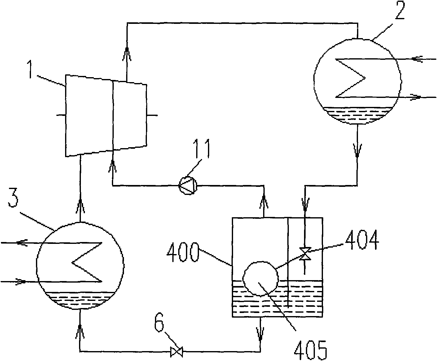
[0018] Below in conjunction with accompanying drawing and specific embodiment the present invention is described in further detail:

[0019] Depend on image 3 , Figure 4 , Figure 5 It can be seen that the present invention includes: a compressor 1, a condenser 2, and an evaporator 3; a flash cylinder 400 is also included; the liquid inlet 401 at the upper end of the flash cylinder 400 is connected to the condenser 2, and the gas outlet 402 at the upper end passes through The one-way valve 11 is connected with an input port of the compressor 1, and the liquid outlet port 403 at the lower end is connected with the evaporator 3 through the second throttle valve 6; the flash cylinder 400 includes: a pair of liquid inlet ports 401 connected coaxial throttling orifice 404; one of the coaxial throttling orifice 404 is fixed and the other rotates; a floating ball mechanism 405 placed on the liquid; the floating ball mechanism 405 is connected with the joint One of the orifice pl...


PUM


Abstract

The invention relates to a vapor compression refrigeration unit comprising a compressor, a condenser, an evaporator and a flash evaporation cylinder. A liquid inlet at the upper end of the flash evaporation cylinder is connected with the condenser, an air outlet at the upper end of the flash evaporation cylinder is connected with an input port of the compressor through a one-way valve, and a liquid outlet at the lower end of the flash evaporation cylinder is connected with the evaporator through a second throttle valve. The flash evaporation cylinder internally comprises a pair of coaxial throttle orifice plates connected with the liquid inlet, a floating ball mechanism, a liquid baffle extending into the liquid, and a liquid level protection mechanism, wherein one of the coaxial throttle orifice plates is fixed, and the other one rotates; the floating ball mechanism is arranged on the liquid and connected with one of the coaxial throttle valve plates; the baffle plate extending into the liquid is arranged between the liquid inlet and the air outlet; and the liquid level protection mechanism is arranged at a position near the air outlet. The invention has the advantages that the vapor compression refrigeration unit can effectively control the liquid level of refrigerating fluid in the flash evaporation cylinder in time and can well automatically adapt to the running under variable working conditions (partial load working condition and variable working conditions of the condenser) of the compressor.

Description

technical field [0001] The invention relates to a vapor compression refrigeration unit, in particular to an economizer in the vapor compression refrigeration unit. Background technique [0002] A common compression refrigeration system consists of four components: an evaporator, a compressor, a condenser, and an expansion device, as well as two-phase flow pipes connecting these four components. [0003] In addition to the above basic components, the refrigeration system may also include other components to improve the thermodynamic efficiency of the refrigeration system. Especially in the low-temperature refrigeration system, in order to improve the cooling capacity and efficiency of the refrigeration system, the refrigeration system usually includes an economizer circuit. Such applications of economizer circuits are well known in the field of refrigeration. It is a general term for assembling economizer circuits and screw compressor units with intermediate air holes on a ...

Claims


Application Information

Patent Timeline
Patent Type & Authority Applications(China)
IPC IPC(8): F25B1/00
Inventor 吴小网陈立
Owner SHANGHAI HANYE REFRIGERATION MACHINERY
Why Eureka
Try Eureka