Stripline-style ferrite phase shifter based on LTCC technology

A ferrite and phase shifter technology, applied in waveguide devices, electrical components, circuits, etc., can solve the difficulty of miniaturization, the complex structure of ferrite phase shifters, and the lack of miniaturized LTCC stacked structure ferrite Volume phase shifter and other issues to achieve the effect of volume and quality reduction

Active Publication Date: 2009-10-14
东莞成电创新电子科技有限公司
View PDF0 Cites 11 Cited by
  • Summary
  • Abstract
  • Description
  • Claims
  • Application Information

AI Technical Summary

Benefits of technology

The new type of device described by this patented technology has several advantages compared to previous designs: it reduces its size while still being effective at transmitting signals between different parts or systems; making it easier for users to integrate them into their own equipment without adding extra weight on certain areas that are needed.

Problems solved by technology

This patents discusses different ways to make small lithium ion batteries that work well at low temperatures without losing their ability to transmit signals or perform functions properly due to changes caused during operation. However, current methods require complicated structures involving multiple components like iron oxide particles and copper plating layers, making them challenging to manufacture smaller versions suitable for incorporation into electronic products.

Method used


Image

  • Stripline-style ferrite phase shifter based on LTCC technology
  • Stripline-style ferrite phase shifter based on LTCC technology
  • Stripline-style ferrite phase shifter based on LTCC technology

Examples


Embodiment Construction

[0025] The present invention will be described in further detail below with reference to a specific implementation and the accompanying drawings, but the embodiments of the present invention are not limited thereto.

[0026] The specific implementation of the LTCC laminated stripline ferrite phase shifter has a center frequency of about 9.2GHz, a bandwidth of more than 300MHz, an insertion loss within the bandwidth of <2dB, a standing wave ratio of VSWR≤1.5, and a phase shift of more than 270 degrees. The length, width and height of the ferrite phase shifter are only about 20mm, 10mm and 4mm, which are much smaller than conventional waveguide type and microstrip type ferrite phase shifters.

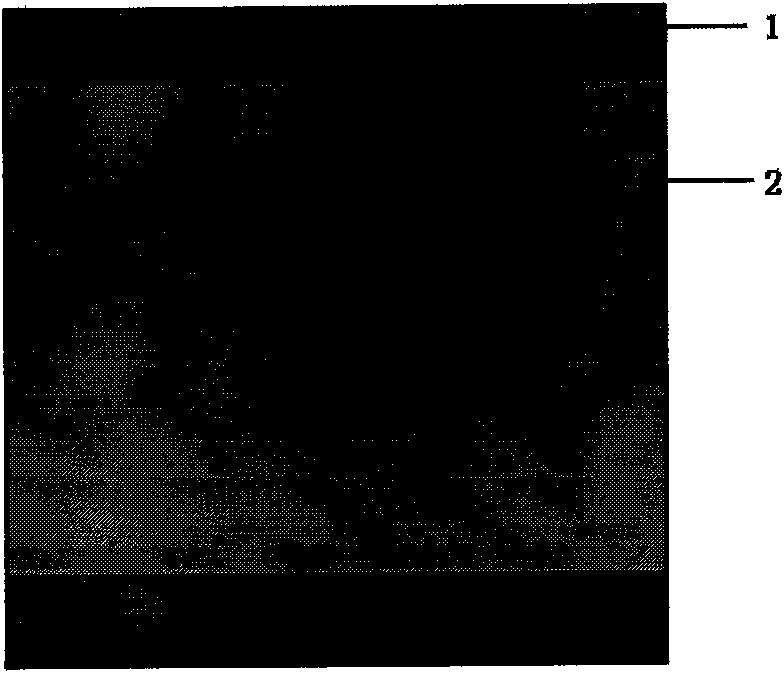
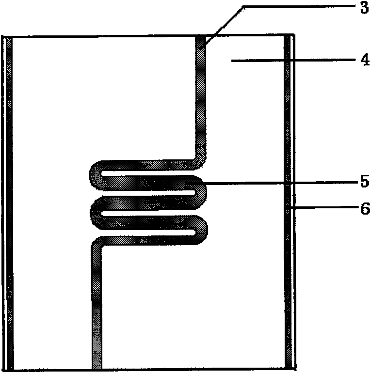
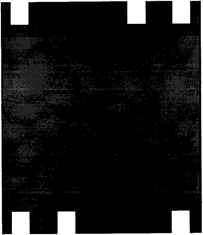
[0027] Figure 1 ~ Figure 4 It is a schematic diagram of each layer and the whole structure of the LTCC laminated stripline ferrite phase shifter. The main structures include:

[0028] The lower ferrite substrate is formed by stacking 15 sheets of low-temperature sintered gyromagnetic l...


PUM


Abstract

A stripline-style ferrite phase shifter based on LTCC technology belongs to the technology of the short-wave communication device. The whole phase shifter is composed of two-layer rectangle gyromagnetic ferrite substrates clamping two-layer rectangle ceramic dielectric substrates, two paralleled magnetizing current leads and one bending microstrip line used for dephasing are clipped by the two-layer ceramic dielectric substrates; the two sides of the ferrite substrates exceeding the ceramic dielectric substrates in width are communicated with each other and form an enclosed magnetic loop. When the device is working, a ring shape silver electrode on the surface of the ferrite substrates is earthed, the impulse magnetization current is exerted to magnetize the gyromagnetic ferrite loop by the magnetizing current leads, the gyromagnetic ferrite substrates are working in remanence state after getting rid of magnetizing current; microwave signal is connected between the two termination electrodes of the bending microstip lines used for dephasing, and non-reciprocal differential phase shift is generated. Compared with the existing phase shifter, the volume and quality of the phase shifter in the invention can be greatly reduced, which is in favor of realizing the integration of phase shifter, active/passive devices and components.

Description


Claims


Application Information

Patent Timeline
Owner 东莞成电创新电子科技有限公司
Why Eureka
Try Eureka