Quick connecting device for punch top and mandril of perforator

A technology of quick connection and head ejector, applied in the direction of metal rolling, manufacturing tools, mandrels, etc., can solve the problems that the thread of the plug cannot be aligned with the thread of the union, the large disassembly tool cannot be used, and it is difficult to rotate the plug. The effect of reducing the workload of workers, simplifying the steps of online head replacement, and reducing the labor intensity of workers

Active Publication Date: 2009-10-21
TAIYUAN HEAVY IND
0 Cites 7 Cited by

AI-Extracted Technical Summary

Problems solved by technology

Due to the increased mass of the plug, workers often cannot align the thread of the plug with the thread of the union when installing the plug, and it is also difficult to rotate the plug when screwing the thread
Since the thread of the plug and union is getting tighter and tighter, it is more diffi...

Abstract

The invention discloses a quick connecting device for a punch top and a mandril of a puncher, and relates to a perforating tool of a seamless steel tube perforator. The quick connecting device comprises the punch top, the mandril and a loose joint connecting the punch top and the mandril, wherein the loose joint consists of a punch top loose joint and a mandril loose joint; one end of the punch top loose joint is provided with outside threads, while the other end is a guide cone of which the outer wall is provided with an annular groove, and the end with the threads is connected with the punch top; one end of the mandril loose joint is provided with outside threads, while the other end is a guide taper hole matched with the guide cone, the guide taper hole is provided with a pin hole corresponding to the annular groove in the horizontal direction of the taper hole, and the end with the threads is connected with the mandril; and the cone of the punch top loose joint is inserted into the guide taper hole of the mandril loose joint, and the overlapping position of the annular groove of the punch top loose joint and the pin hole of the mandril loose joint is provided with a positioning pin roll. The quick connecting device can meet the requirement of quick replacement of the punch top on line, improves production efficiency, and can be recycled to reduce production cost.

Application Domain

Technology Topic

Image

  • Quick connecting device for punch top and mandril of perforator
  • Quick connecting device for punch top and mandril of perforator
  • Quick connecting device for punch top and mandril of perforator

Examples

  • Experimental program(1)

Example Embodiment

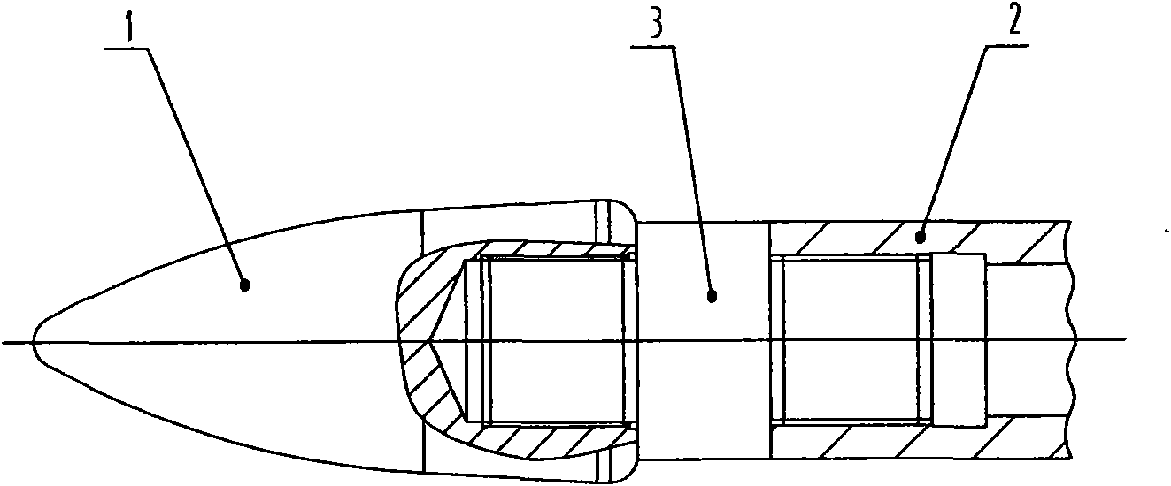
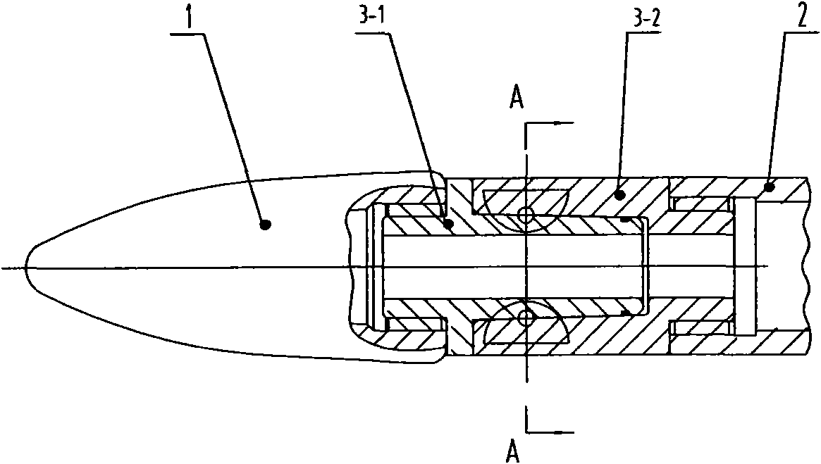
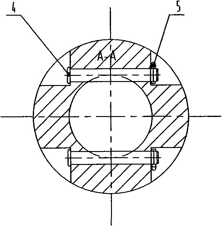
[0012] Such as figure 2 , image 3 As shown, a quick connection device for the ejector rod of the punching machine includes: the ejector 1, the ejector 2, and the active joint 3 connecting the ejector and the ejector; the active joint 3 is composed of the ejector 3-1 and the ejector. It is composed of a live connection 3-2. One end of the plug live connection 3-1 has an external thread, and the other end is a guide cone with an annular groove on the outer wall, and the end with an external thread is connected to the plug 1; the plug live connection 3- 2 One end has an external thread, and the other end is a guide taper hole matching the guide cone, and a pin hole is provided in the transverse direction corresponding to the annular groove, and the end with an external thread is connected to the ejector rod 2; the plug The cone of the live joint 3-1 is matched with the guide taper hole of the mandrel joint 3-2, and the annular groove of the head joint 3-1 coincides with the pin hole of the mandrel joint 3-2 A locating pin 4 is provided at the position, and a split pin 5 is provided in the small hole at the end of the locating pin 4.
[0013] Installation and working process of the present invention:
[0014] The installation work can be carried out under the production line: the end of the plug 3-1 with external thread is connected to the plug 1, and the end of the plug 3-2 with external thread is connected with the plug 2. Replacement work on the production line: After the ejector pin is installed in place, align the plug 3-1 and plug 1 with its conical end and align the end of the ejector pin with 3-2 with a guide taper hole, and insert it to the plug. After the center line of the annular groove on the joint 3-1 coincides with the center line of the pin hole of the mandrel joint 3-2, insert the two positioning pins 4 into the two pin holes of the mandrel joint 3-2 respectively. Then insert a split pin 5 into the end hole of the positioning pin 4, and work can be started after the installation is completed. When replacing the plug, remove the split pin 5 and pull out the positioning pin 4. The plug joint 3-1 and plug 1 can be removed as a whole for replacement. After the ejector 1 and ejector 2 are scrapped, the ejector joint 3-1 and ejector joint 3-2 can be removed and used. Since the plug joint 3-1 and the mandrel joint 3-2 are made of more expensive alloys, recycling can reduce the use cost.

PUM

no PUM

Description & Claims & Application Information

We can also present the details of the Description, Claims and Application information to help users get a comprehensive understanding of the technical details of the patent, such as background art, summary of invention, brief description of drawings, description of embodiments, and other original content. On the other hand, users can also determine the specific scope of protection of the technology through the list of claims; as well as understand the changes in the life cycle of the technology with the presentation of the patent timeline. Login to view more.

Similar technology patents

Full-automatic hot and sour rice noodle maker

InactiveCN108113037AHigh degree of automationReduce worker workloadFood shapingMicrophoneEngineering
Owner:重庆自然红商贸有限公司

Egg white and yolk separation production line

PendingCN113180137AImprove removal efficiencyReduce worker workloadProtein composition from eggsHollow article cleaningFeed driveEngineering
Owner:开平市旭日蛋品有限公司 +1

Classification and recommendation of technical efficacy words

  • Reduce worker workload
  • Reduce replacement time

Automatic detection equipment

InactiveCN105598043AHigh automation efficiencyReduce worker workloadSortingEngineeringAutomatic test equipment
Owner:SUZHOU AMITY ELECTRONICS & PLASTICS

Diagnosis system of high-voltage switch cabinet partial discharge signal

PendingCN109031069AReduce worker workloadNo subjectivity and limitationsTesting dielectric strengthVIT signalsPartial discharge
Owner:LINFEN POWER SUPPLY COMPANY OF STATE GRID SHANXI ELECTRIC POWER +1

Capacitor clamp

InactiveCN103745839AReduce worker workloadReduce fatigue strengthMeasurement instrument housingCapacitor manufactureCapacitanceEngineering
Owner:广州市番禺桂博自动化设备制造厂

Converter bottom blowing air brick, special drilling machine and quick thermal replacement method of air brick

ActiveCN102676730AReduce replacement timeGood high temperature strength and thermal shock resistanceManufacturing convertersElectrical and Electronics engineeringCorundum
Owner:宣化钢铁集团有限责任公司 +2
Why Eureka
Try Eureka