Double-cycloid rotor variable pump

A variable displacement pump and rotor technology, applied in the direction of rotary piston pumps, pumps, rotary piston machinery, etc., can solve the problems of small flow adjustment range, easy to jam blades, complex variable mechanism, etc., and achieve large flow adjustment range and high flow rate. The effect of simple adjustment and simple variable mechanism

Inactive Publication Date: 2009-10-21
SHANGHAI NORMAL UNIVERSITY
View PDF0 Cites 4 Cited by
  • Summary
  • Abstract
  • Description
  • Claims
  • Application Information

AI Technical Summary

Problems solved by technology

[0003] The structure of the vane pump is complicated, the manufacture is difficult, and it is sensitive to the rotational speed of the shaft. It cannot work normally if it is too fast or too slow.
At high speed, the pressure difference between the two ends of the blade will easily cause the blade to detach from the surface of the stator, causing the blade to fall out of the air
Under high pressure, the surface of the vane and the stator is easy to wear, the flow adjustment range is small, and the variable mechanism is complicated
[0004] The plunger pump has a complex structure, many parts, difficult manufacture, and high price. It is mostly used as a high-pressure pump. Similar to the vane pump, this pump has high requirements for oil, and the plunger is easy to be stuck after dirty oil. High speed, and the variable mechanism is very complicated
[0005] As is well known, the double cycloid rotor pump has many advantages, but the rotor pumps so far do not have the function of variable volume adjustment

Method used


Image

  • Double-cycloid rotor variable pump
  • Double-cycloid rotor variable pump

Examples


Embodiment Construction

[0030] The present invention will be further described below in conjunction with accompanying drawing and specific embodiment:

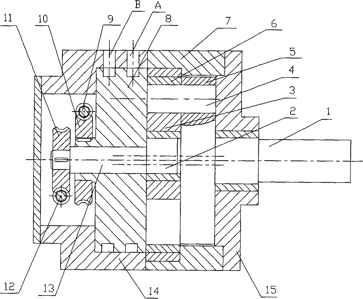
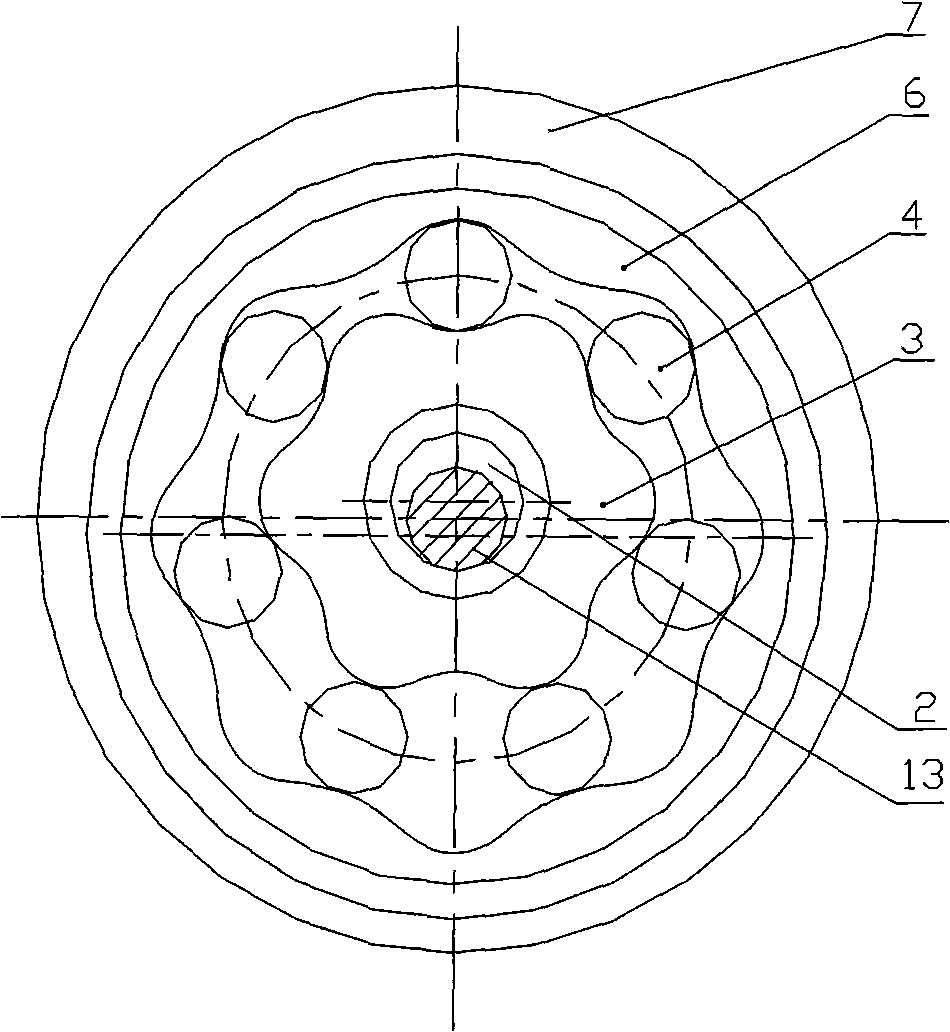
[0031] A variable variable double cycloidal rotor pump, the pump is mainly composed of a transmission shaft 1, an eccentric shaft 2, an inner rotor 3, pin teeth 4, a turntable 5, an outer rotor 6, a casing 7, a flow distribution plate 8, a position adjustment mechanism, and a variable mechanism , Rear end cover 14 and front end cover 15 are formed. The pin teeth 4 and the rotating disc 5 constitute a pin wheel. The inner rotor 3, the pin teeth 4 and the outer rotor 6 form several closed tooth cavities, and these tooth cavities communicate with the oil inlet and outlet through the oil distribution plate 8. The inner rotor 3 is a short epicycloidal gear, supported by bearings, and installed on the eccentric shaft 2. The rotation axis of the eccentric shaft 2 coincides with the rotation axis of the pin wheel formed by the pin teeth 4 and the turntable ...


PUM


Abstract

The invention relates to a rotor pump structure which can change flow rate, in particular to a double-cycloid rotor variable pump; a rear end cover (14) is internally provided with a valve plate (8) which is provided with an oil inlet (A) and an oil outlet (B); a variable shaft (13) is inserted into the center of the valve plate (8); a variable mechanism is configured on the variable shaft (13); the right end of the variable shaft (13) is fixedly connected with an eccentric shaft (2) with the mutual axis position being deviated; a transmission shaft (1) is inserted into the center of a front end cover (15) and is fixedly connected with a rotating disc (5); a ring of cylindrical pin teeth (4) are arranged on the rotating disc (5) by a cantilever; the pin teeth exposed outside of the cantilever are inserted in a ring groove formed by matching of an outer rotor (6) and an inner rotor (3); and the axis of the front end cover (15) and the center of the circular inner wall of a shell (7) have eccentricity. The flow rate can be changed by rotating the eccentric shaft (2); the adjustment of the flow rate is simple, convenient and easy; and the continuity of absorbing and discharging oil is strong and the requirement to hydraulic oil is not high.

Description

(1) Technical field [0001] The invention relates to a pump structure, in particular to a variable flow rotor pump structure. (2) Background technology [0002] At present, as commonly used variable displacement pumps, there are two kinds of variable displacement vane pumps and variable displacement plunger pumps, each of which has its own advantages and disadvantages. [0003] The structure of the vane pump is complex, difficult to manufacture, sensitive to the rotational speed of the shaft, too fast and too slow can not work normally, high oil requirements, easy to jam the blades after oil contamination, resulting in rapid wear. At high speed, the pressure difference between the two ends of the blade will easily cause the blade to separate from the surface of the stator, resulting in the blade being hollow. Under high pressure, the surfaces of blades and stators are easy to wear, the flow adjustment range is small, and the variable mechanism is complicated. [0004] The p...

Claims


Application Information

Patent Timeline
Patent Type & Authority Applications(China)
IPC IPC(8): F04C2/10
Inventor 林菁
Owner SHANGHAI NORMAL UNIVERSITY
Why Eureka
Try Eureka