Annular balancing piston

A balancing piston, ring-shaped technology, applied in rotary piston/oscillating piston pump components, components of pumping devices for elastic fluids, machines/engines, etc., can solve difficult control, small balance force, pressure Almost the same problem, to achieve the effect of easy control of oil volume

Active Publication Date: 2009-10-21
WUXI COMPRESSOR CO LTD
View PDF0 Cites 2 Cited by
  • Summary
  • Abstract
  • Description
  • Claims
  • Application Information

AI Technical Summary

Problems solved by technology

[0005] 1. The radial gap between the balance piston 3 and the rotor bearing seat 4 is large, and a large amount of pressure oil is lost through the gap, so that the pressure difference between the two sides of the balance piston 3 cannot be increased, and the balance force is small
[0006] 2. The manufacturing tolerance of the inner hole of the rotor bearing seat 4 and the outer circle of the balance piston 3 has a great influence on the area of ​​the ring formed between them, so that the oil flow through the bearing changes greatly and is difficult to control

Method used


Image

  • Annular balancing piston
  • Annular balancing piston
  • Annular balancing piston

Examples


Embodiment Construction

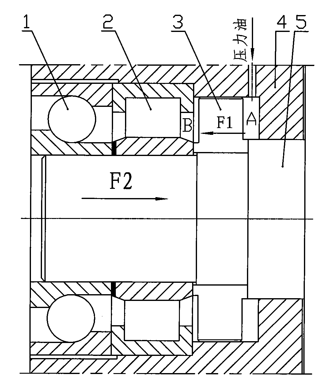
[0018] See figure 2 , is a partial structure using an oil-injected screw compressor of the present invention. The compressor rotor 5 is assembled on the rotor bearing seat 4, and the shaft head of the compressor rotor 5 is equipped with a cylindrical roller bearing 2 for bearing radial force and an angular contact ball bearing 1 for bearing axial thrust. A balance piston 3 is mounted on the shaft of the compressor rotor 5 between the cylindrical roller bearing 2 and the side wall of the rotor bearing housing 4 . The balance piston 3 divides the space between the cylindrical roller bearing 2 and the side wall of the rotor bearing seat 4 into two chambers, namely the pressure oil chamber A and the low pressure bearing chamber B.

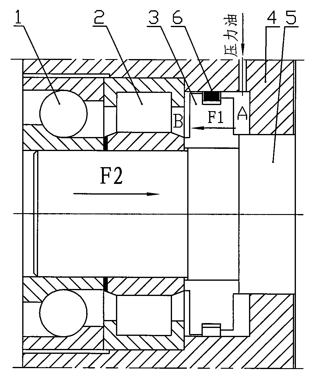
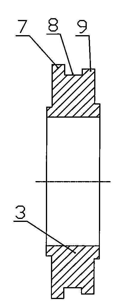
[0019] The present invention is an improvement on the structure of the balance piston 3 described above. An annular groove 8 is arranged on the outer circumference of the piston 3, and the movable device in the annular groove 8 has a piston ring 6, ...


PUM


Abstract

The invention relates to an annular balancing piston used in a bearing base at an exhaust end of an oil-jet screw compressor, an annular groove is formed on the outer circumference of the piston, a movable device in the annular groove is provided with a piston ring, and the outer diameter of the piston ring is larger than the outer diameter of the piston. As the annular groove is formed on the outer circumference of the piston and the movable device in the annular groove is provided with the piston ring, gap is existed between the annular groove and the piston ring; when in use, the piston ring and an inner cavity of the bearing base of a rotor are in close fit, the radial gap between the piston and the bearing base can be eliminated, pressure oil flows out through the gap between the annular groove and the piston ring, and the pressure in a pressure cavity of the bearing base is easy to ensure.

Description

(1) Technical field [0001] The invention relates to an annular balance piston, in particular to a balance piston used in a bearing seat at the discharge end of an oil injection screw compressor. (2) Background technology [0002] When the oil-injected screw compressor is running under load, due to the structural characteristics of the helical rotor, thrust will be generated in the axial direction of the rotor during the meshing compression process. In order to reduce the impact of this axial thrust on the bearing and improve the service life of the bearing, a balance piston is generally added to the bearing seat of the exhaust end of the compressor. [0003] The balance piston structure of the existing oil-injected screw compressor is as follows: figure 1 As shown, it consists of a rotor bearing seat 4, a balance piston 3, and a pressure oil chamber A and a low pressure bearing chamber B on both sides of the balance piston 3. In the figure, 1 is an angular contact ball bea...

Claims


Application Information

Patent Timeline
Patent Type & Authority Applications(China)
IPC IPC(8): F04C29/00
Inventor 许吉清曹勤良张国强周耘
Owner WUXI COMPRESSOR CO LTD
Why Eureka
Try Eureka