Gear angle quick aligning and positioning device for gear grinding and positioning method

A technology for positioning devices and gears, which is applied to gear teeth manufacturing devices, belts/chains/gears, gear teeth, etc., which can solve the problems of high cost, inability to meet the requirements of accurate alignment and positioning of workpiece gear angles, and low production efficiency. Effects of radial clearance, improvement of efficiency and automation level of machine tools, and improvement of precision

Inactive Publication Date: 2020-09-18
秦川机床工具集团股份公司
View PDF5 Cites 0 Cited by
  • Summary
  • Abstract
  • Description
  • Claims
  • Application Information

AI Technical Summary

Problems solved by technology

[0003] When traditional gear grinding is used to find the initial position of the gear angle, the grinding wheel is placed close to the workpiece gear, the gap uniformity between the grinding wheel and the tooth surface of the gear to be ground is manually checked, and the size of the sparks generated by the trial grinding of the tool is observed to judge the gear start. Whether the starting angle position is correct or not, the operation is random, the quality stability is poor, the production efficiency is low, the labor intensity is high, and it cannot meet the requirements of mass production and automatic processing of machine tools
At present, there are also some

Method used


Image

  • Gear angle quick aligning and positioning device for gear grinding and positioning method
  • Gear angle quick aligning and positioning device for gear grinding and positioning method
  • Gear angle quick aligning and positioning device for gear grinding and positioning method

Examples


Example Embodiment

[0028] The present invention will be described in detail below with reference to the accompanying drawings. Obviously, the described embodiments are only a part of the embodiments of the present invention, but not all of the embodiments. Based on the embodiments of the present invention, all other embodiments obtained by persons of ordinary skill in the art without creative efforts shall fall within the protection scope of the present invention.
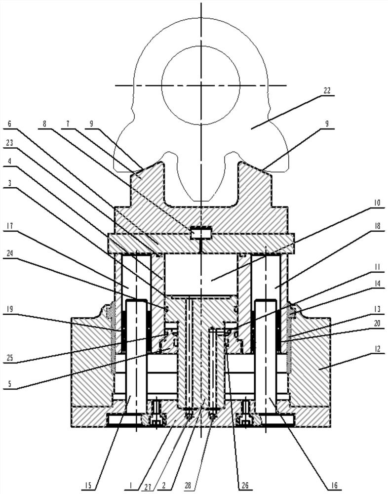
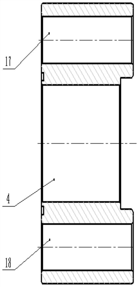
[0029] like figure 1 As shown in the figure, the present invention provides a gear angle quick alignment and positioning device for gear grinding, which includes a base plate 1 installed on a machine tool table, a piston 3 is fixedly arranged in the center of the base plate 1, and an integral structure is arranged on the piston 3. The piston rod 2, the piston 3 is sleeved with an oil cylinder 4, the outer wall of the piston 3 is in close contact with the inner wall of the oil cylinder 4; The alignment tool setting mechanism, the oil...


PUM


Abstract

The invention discloses a gear angle quick aligning and positioning device for gear grinding and a positioning method. The gear angle quick aligning and positioning device for gear grinding comprisesa bottom plate mounted on a working table of a machine tool, a piston is fixedly arranged in the center of the bottom plate, an oil cylinder is arranged on the piston in a sleeving mode, and the outerwall of the piston is in close contact with the inner wall of the oil cylinder; an oil cylinder end cover is mounted at one end of the oil cylinder, an aligning and tool-setting mechanism matched with a workpiece gear is mounted at the other end of the oil cylinder, and the oil cylinder end cover is arranged on a piston rod of the piston in a sleeving mode and is in sealed connected with the piston rod; a first oil circuit and a second oil circuit are formed in the piston to communicate with a first working oil cavity and a second working oil cavity correspondingly; and when the first oil circuit works, the aligning and tool-setting mechanism is driven to move upwards to complete tool-setting positioning, and when the second oil circuit works, the aligning and tool-setting mechanism is driven to move downwards to complete tool retracting. Quick aligning and precise positioning of the workpiece angle can be realized, positioning stability is good, and the quality and efficiency of batch machining and the automation level of the machine tool are improved.

Description

technical field [0001] The invention relates to the technical field of gear grinding machines, in particular to a gear angle quick alignment and positioning device and a positioning method for gear grinding. Background technique [0002] The automobile industry is an industry that requires mass production and processing. The development of the automobile industry requires that the sector gear of the steering gear rocker shaft be improved from the gear shaping process to the gear grinding process. Whether the sector gear of the rocker arm shaft of the steering gear can automatically and quickly find the angle starting position of the gear when grinding the gear directly affects the quality stability and production efficiency of the mass-processed gear. [0003] When traditional gear grinding is used to find the starting position of the gear angle, the grinding wheel is placed close to the workpiece gear, the gap uniformity between the grinding wheel and the tooth surface of t...

Claims


Application Information

Patent Timeline
IPC IPC(8): B23F23/06B23F23/12
CPCB23F23/06B23F23/12
Inventor 霍毅
Owner 秦川机床工具集团股份公司
Why Eureka
Try Eureka