
Wind and light complementary beacon light device

A technology of wind-solar complementary and navigation lights, applied in the field of navigation lights, can solve the problems of power controller failure, no typhoon prevention measures, and limited system power, and achieve the effect of changing quality, changing response to bad weather, and abundant wind resources

Inactive Publication Date: 2011-04-20
象山欧曼机电有限公司
View PDF0 Cites 0 Cited by
  • Summary
  • Abstract
  • Description
  • Claims
  • Application Information

AI Technical Summary

Problems solved by technology

[0002] The use of wind energy to generate lighting and apply it to transportation facilities has a history of hundreds of years. Although the basic form has been continuously improved, it cannot leave the traditional style: that is, the propeller-shaped windmill is linked with the wind generator, and the long tail rotates with the wind direction. There are many problems in this traditional structural form: the wind blades rotating in a large arc are easy to be damaged, occasionally encountering strong winds often hurt people, there are hidden dangers of accidents, and the wind turbines are exposed to the outside and are easy to corrode and damage
There are abundant wind resources in the sea, and it is an ideal solution to implement wind and solar complementarity. This solution has long been proposed, but it is difficult to apply it in practice because there are no reliable typhoon protection measures.
This problem can be solved with a conventional power controller, but the power of the whole system is limited. If the typhoon lasts for a long time, the power controller will fail

Method used


Image

  • Wind and light complementary beacon light device
  • Wind and light complementary beacon light device
  • Wind and light complementary beacon light device

Examples


Embodiment Construction

[0020] Below in conjunction with accompanying drawing and embodiment the invention will be further described:

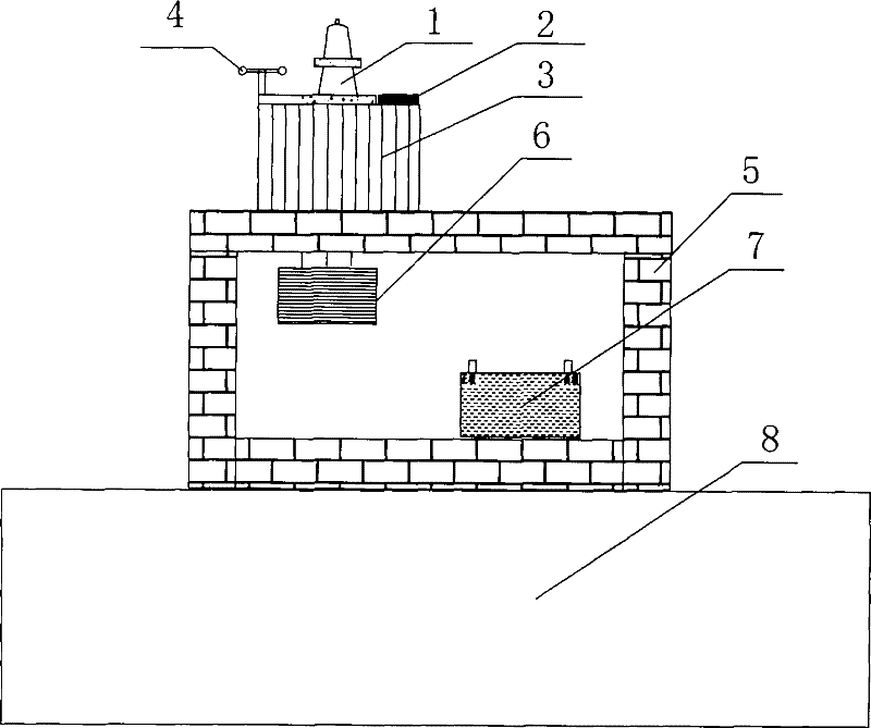
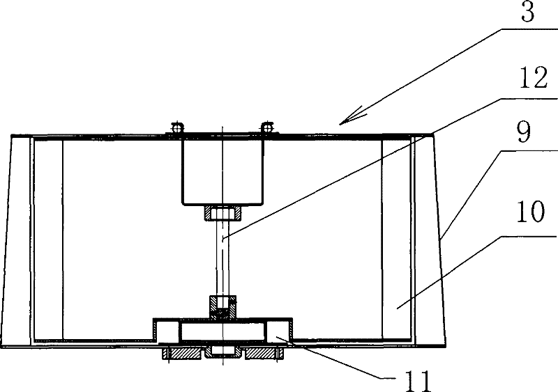
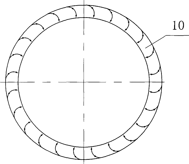
[0021] As shown in the figure, this wind-solar complementary navigation light device mainly includes a navigation light 1, a wind wheel 10, a generator 11, a battery pack 7 and a controller 6, and the wind power generator 3 is fixedly installed on the base 5, The base 5 is mounted on a light tower 8 . The rotating shaft 12 of the wind rotor 10 is connected to the input end of the generator 11 , and the wind rotor 10 , the rotating shaft 12 and the generator 11 constitute the wind power generator 3 . The blades of the wind wheel 10 are parallel to the rotating shaft 12, and are distributed in a grid shape to form a cylindrical wind wheel with the rotating shaft 12 as the axis. The outer periphery of the wind wheel 10 is provided with an air deflector 9, and the wind deflector 9 is arranged in a grid shape. The distributed guide plates form a cylindrical shape with th...


PUM


Abstract

The invention relates to a wind and light complementary beacon light device. The beacon light device mainly comprises a beacon light, a wind wheel, a generator, a storage battery and a controller. A rotating shaft of the wind wheel is connected with an input terminal of the generator; and the wind wheel, the rotating shaft and the generator form a wind mill generator. The blades of the wind wheelare in parallel with the rotating shaft and are distributed in a fence form to form a cylindrical wind wheel centering on the rotating shaft. The wind mill generator is provided with a mechanical sensing automatic brake device which is used for adjusting the brake force according to the size of the wind power; and a damp output shaft of the mechanical sensing automatic brake device is connected with an input shaft of the generator. The wind and light complementary beacon light device has the advantages that: the series of the vertical axis wind and light complementary beacon lights solve a plurality of problems of the conventional propeller type wind mill; and the device adopts the wind mill generating device with a novel vertical axis structure and the anti-typhoon mechanical sensing automatic brake device so as to greatly improve the quality of the beacon light and the function of the beacon light resisting the rough weather.

Description

technical field [0001] The invention mainly relates to the field of navigation lights, and mainly relates to a wind-solar complementary navigation light device. Background technique [0002] The use of wind energy to generate lighting and apply it to transportation facilities has a history of hundreds of years. Although the basic form has been continuously improved, it cannot leave the traditional style: that is, the propeller-shaped windmill is linked with the wind generator, and the long tail rotates with the wind direction. There are many problems in this traditional structural form: the wind blades rotating in a large arc are easy to be damaged, occasionally encountering strong winds often hurt people, and there are hidden dangers of accidents, and the wind turbine is exposed and easy to corrode and damage. The navigation lights commonly used at present all use solar energy as the energy source, and there is a danger of power failure in case of rainy weather for a long t...

Claims


Application Information

Patent Timeline
Patent Type & Authority Patents(China)
IPC IPC(8): F21S9/00F21S9/02F21S9/03F21S9/04F03D9/00H02K7/18F21W111/04F03D9/11F03D9/43
CPCY02E10/72Y02B10/30Y02E70/30
Inventor 黄兆峰
Owner 象山欧曼机电有限公司
Learn More