Apparatus and method for changing image quality in real time in a digital camcorder

a digital camcorder and image quality technology, applied in the field of digital camcorders, can solve the problems of increasing the parameter value, reducing the image quality, and requiring a larger memory spa

Inactive Publication Date: 2005-10-20
SAMSUNG ELECTRONICS CO LTD
View PDF4 Cites 16 Cited by
  • Summary
  • Abstract
  • Description
  • Claims
  • Application Information

AI Technical Summary

Benefits of technology

[0018] It is, therefore, an object of the present invention to provide a moving image photographing apparatus for enabling a user to dynamically adjust an image quality by considering a required photographing time and / or a desired image quality while photographing a moving image using a digital camcorder, and a method for changing the image quality in real time.

Problems solved by technology

However, a conventional digital camcorder records picture or moving image data in a limited memory space.
However, an increase in the parameter value decreases an image quality but requires less memory storage space.
In addition, an increase in the FPS, which indicates a high-quality moving image, requires a larger memory space.
In some cases, therefore, the user may photograph a less-important image at the image quality set for a highly-important image, making inefficient use of the limited memory.
In order to prevent inefficient use of the memory, the user should inconveniently stop the ongoing photographing and set a desired new mode, which can result in the interruption of the photographing of a moving image.
In order to prevent this inconvenience, the user should purchase a separate internal or external memory, which, however, increases the purchasing cost.

Method used


Image

  • Apparatus and method for changing image quality in real time in a digital camcorder
  • Apparatus and method for changing image quality in real time in a digital camcorder
  • Apparatus and method for changing image quality in real time in a digital camcorder

Examples


Embodiment Construction

[0035] An embodiment of the present invention will now be described in detail with reference to the accompanying drawings. In the following description, a detailed description of known functions and configurations incorporated herein has been omitted for conciseness.

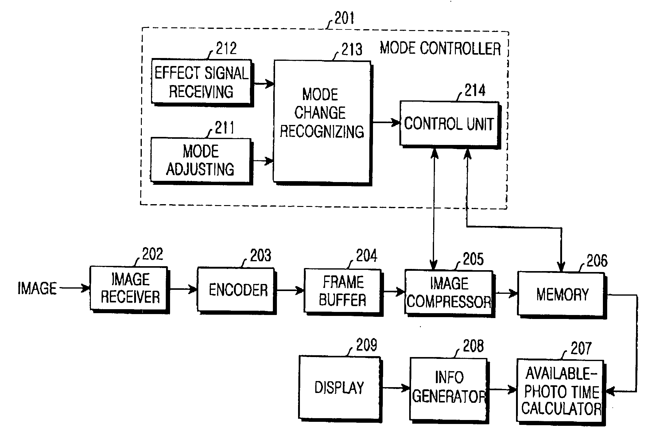
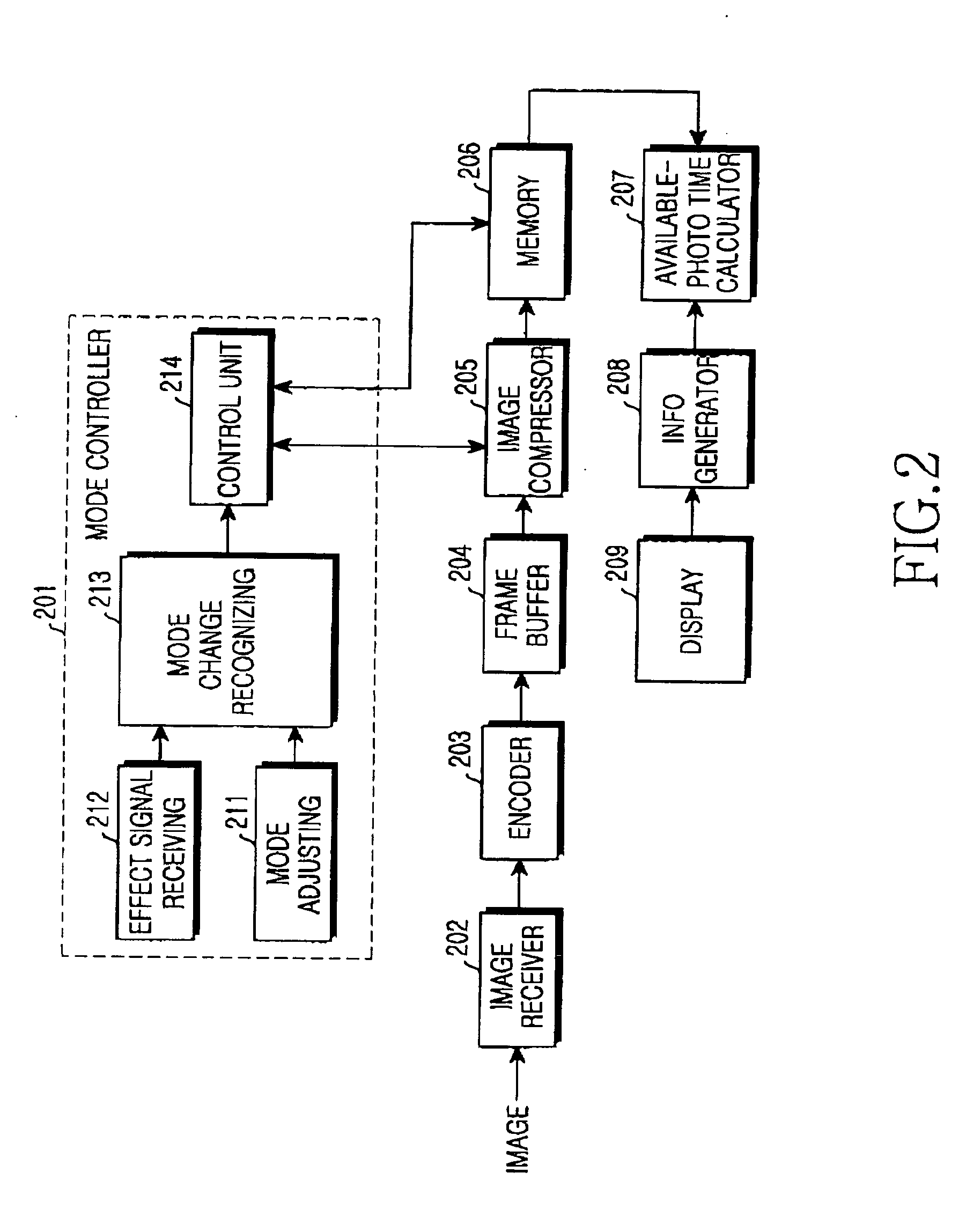
[0036]FIG. 2 is a block diagram schematically illustrating a structure of a digital camcorder according to an embodiment of the present invention. As illustrated, an internal structure of a digital camcorder according to an embodiment of the present invention includes a mode controller 201, an image receiver 202, an encoder 203, a frame buffer 204, an image compressor 205, a memory 206, an available-photographing time calculator 207, an information generator 208, and a display 209.

[0037] The mode controller 201 includes a mode adjusting unit 211, an effect signal receiving unit 212, a mode change recognizing unit 213, and a control unit 214. The mode adjusting unit 211 provides mode change means such as a menu for chan...


PUM


Abstract

Apparatus and method are provided for changing an image quality storage in real time. In the apparatus and method, an effect signal receiving unit receives an image mode change request signal from a user while photographing an image. A mode change recognizing unit determines an image mode in response to an output signal of the effect signal receiving unit, and generates an image quality adjust command according to the determination result. A control unit generates a mode control signal for changing an image mode of a moving image in response to the image quality adjust command output from the mode change recognizing unit. An image compressor compresses an input image according to the mode control signal output from the control unit.

Description

PRIORITY [0001] This application claims the benefit under 35 U.S.C. § 119(a) of an application entitled “Apparatus and Method for Changing Image Quality in Real Time in a Digital Camcorder” filed in the Korean Intellectual Property Office on Mar. 23, 2004 and assigned Serial No. 2004-19712, the entire contents of which are incorporated herein by reference. BACKGROUND OF THE INVENTION [0002] 1. Field of the Invention [0003] The present invention relates generally to a digital camcorder for storing an input moving image in a digital storage medium or a mobile phone with a moving image photographing function. In particular, the present invention relates to an apparatus and method for changing an image quality of a moving image photographed by a user and storing the moving image by using a compression scheme corresponding to the changed image quality in a a digital storage medium, such as a digital camcorder or a mobile phone with a camera (also known as a camera phone). [0004] 2. Descr...

Claims


Application Information

Patent Timeline
Patent Type & Authority Applications(United States)
IPC IPC(8): H04N5/77H04N5/781H04N7/01H04N5/907H04N7/12H04N9/79H04N9/804
CPCH04N5/772H04N5/781H04N9/8047H04N9/7921H04N9/8042H04N5/907E02B3/066E02B3/123
Inventor JUNG, KYUNG-HUN
Owner SAMSUNG ELECTRONICS CO LTD
Why Eureka
Try Eureka