Signal reproducing apparatus and method, signal recording apparatus and method, signal receiver, and information processing method

a signal reproducing and signal recording technology, applied in combination recording, record information storage, analogue secracy/subscription systems, etc., can solve the problem of not achieving satisfactory characteristic value, unable to achieve optimal actual perception of noise, and inability to introduce quantization accuracy based on a more advanced auditory model in the futur

Inactive Publication Date: 2006-11-21
SONY CORP
View PDF15 Cites 15 Cited by
  • Summary
  • Abstract
  • Description
  • Claims
  • Application Information

AI Technical Summary

Benefits of technology

[0027]In view of the foregoing status of the art, it is an object of the present invention to provide a signal reproducing device and method, a signal recording device and method, a signal receiving device, and an information processing method in which trial viewing / listening is possible, the possibility of decryption can be eliminated by not encrypting a part of a signal, the quality (sound quality or image quality) of trial viewing / listening can be arbitrarily changed, and the quality of a signal to be enjoyed after the purchase can be confirmed while the quality of a signal of trial viewing / listening is insufficient.

Problems solved by technology

As this method is used, a person who acquired the key signal can correctly reproduce the acoustic signal and a person who did not acquire the key signal can only reproduce noise.
In this system, though the quantization noise spectrum is flat and the noise energy is minimum, the actual perception of noise is not optimum because the auditory masking effect is not utilized.
With this technique, however, even when measuring characteristics by using a sine wave input, a satisfactory characteristic value is not obtained because of fixed bit allocation.
Therefore, control of the quantization accuracy based on a more advanced auditory model cannot be introduced in the future.
As this method is used, only a person who acquired the key signal can correctly reproduce the acoustic signal and a person who did not acquire the key signal can only reproduce noise.
However, in these scrambling methods, if there is no key or if software is reproduced by ordinary reproducing means, what is reproduced is noise and the content of the software cannot be grasped.
Therefore, these method cannot be used for applications such as distributing a disc having music recorded thereon with relatively low sound quality and allowing a person who listens to the music on trial to purchase only a key for a tune which the person likes and to reproduce the tune with high sound quality, or allowing a person to listen the software on trial and then to newly purchase a disc on which the software is recorded with high sound quality.
Conventionally, in the case of encrypting a high-efficiency coded signal, it is difficult to prevent the compression efficiency from lowering while providing a code string which is significant to ordinary reproducing means.
Moreover, if the scrambled code string is not conformable to the original high-efficiency coding standard, the reproducing means might not operate at all.
On the other hand, if the quantity of information is reduced, for example, by utilizing the auditory characteristics in the case where a PCM signal is scrambled and then high-efficiency coded, the signal obtained by scrambling the PCM signal cannot necessarily reproduced when the high-efficiency coding is canceled.
Therefore, it is difficult to correctly descramble the signal.
In the case of low quality (sound quality or image quality) of trial viewing / listening, what quality of signal can be enjoyed after the purchase is unknown and whether to purchase or not is difficult to decide.

Method used


Image

  • Signal reproducing apparatus and method, signal recording apparatus and method, signal receiver, and information processing method
  • Signal reproducing apparatus and method, signal recording apparatus and method, signal receiver, and information processing method
  • Signal reproducing apparatus and method, signal recording apparatus and method, signal receiver, and information processing method

Examples


Embodiment Construction

[0078]Prior to the description of embodiments of the present invention, an optical recording / reproducing device as a typical compressed data recording / reproducing device used for the description of the embodiments of the present invention will be first described with reference to the drawings.

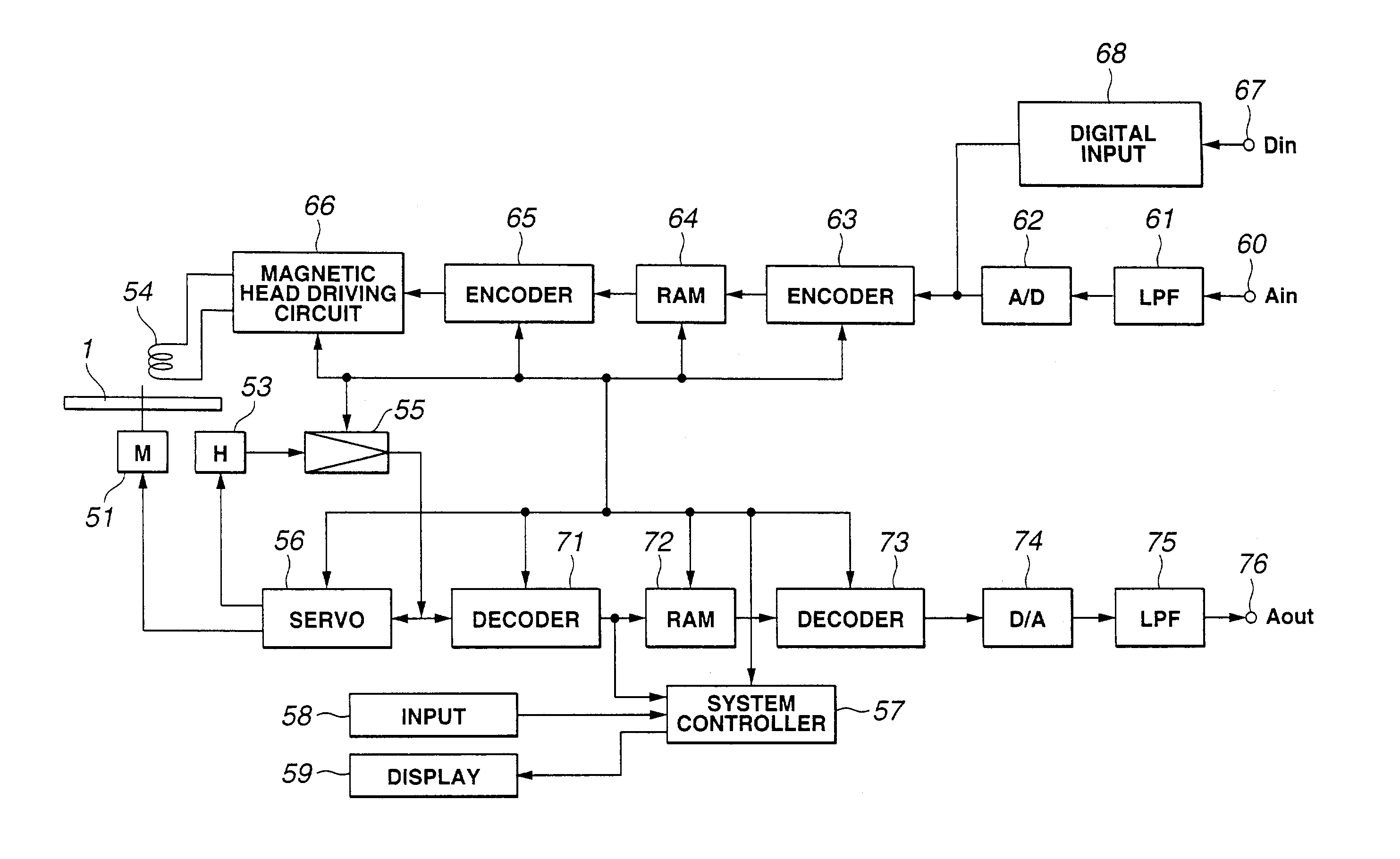
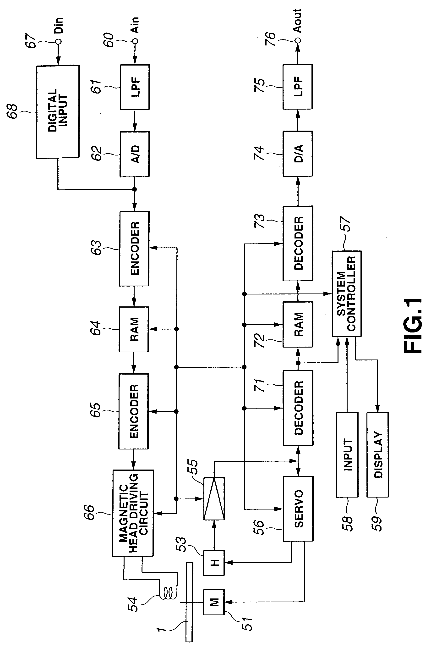
[0079]FIG. 1 is a block diagram showing an exemplary optical disc recording / reproducing device. In the device shown in FIG. 1, first, a magneto-optical disc 1 rotationally driven by a spindle motor 51 is used as a recording medium. When recording data to the magneto-optical disc 1, for example, a modulation magnetic field corresponding to the data to be recorded is applied by a magnetic head 54 while a laser beam is cast by the optical head 53, thus performing so-called magnetic field modulation recording so as to record the data along recording tracks of the magneto-optical disc 1. When reproducing data, the recording tracks of the magneto-optical disc 1 are traced by a laser beam from the mag...


PUM

PropertyMeasurementUnit
lengthaaaaaaaaaa
variable-lengthaaaaaaaaaa
frequencyaaaaaaaaaa

Abstract

A signal (801) of a first code string made through replacing a part of a code string of a predetermined format with dummy data is sent to code string rewriting means (1802) via code string resolution means (1801). A signal (806) of a second code string for complementing the dummy data part in the signal (801) is sent to the code string rewriting means (1802) via control means (1805) and the dummy data in the first code string is rewritten to the second code string. At the time of trial viewing/listening, a signal (802) from the code string resolution means (1801) is selected by a switch (1808), and when the second code string (806) is acquired through content purchase, a signal (803) from the code string rewriting means (1802) is selected by the switch (1808). Thus, trial viewing/listening of a content such as music is made possible while the possibility of decryption is eliminated. By acquiring a relatively small quantity of data, reproduction of a high-quality content is made possible.

Description

TECHNICAL FIELD[0001]This invention relates to a signal reproducing device and method, a signal recording device and method, a signal receiving device, and an information processing method, and for example, to a signal reproducing device and method, a signal recording device and method, a signal receiving device, and an information processing method which perform coding of a signal so as to enable trial viewing / listening, and thus enable reproduction or recording the signal with high quality by adding of data of a small amount of information to the signal if a trial viewer / listener decides to purchase the signal.BACKGROUND ART[0002]A content (software) distribution method is known in which, for example, an acoustic signal or the like is encrypted and then broadcast or recorded to a recording medium so that only a person who purchased a key for decryption is permitted to listen to the signal.[0003]As an encryption method, for example, a method is known in which an initial value of a ...

Claims


Application Information

Patent Timeline
Patent Type & Authority Patents(United States)
IPC IPC(8): G06F7/04G09C3/00H03M7/00H04N5/92G06F21/10G07F17/16G10K15/02G10L19/00G10L19/02G11B20/00G11B20/10G11B20/12G11B27/034G11B27/10G11B27/30H03M7/30H04N7/24H04N21/2343H04N21/2347H04N21/462H04N21/4627H04N21/472H04N21/81H04N21/8549
CPCG11B20/0071G11B20/00818G11B20/00978G11B20/10527G11B27/034G11B27/105H04N21/234345H04N21/234354H04N21/23476H04N21/4621H04N21/4627H04N21/47211H04N21/8113H04N21/8549G06Q20/12G06Q20/123G06Q20/1235G06Q30/06G07F17/0014G11B20/00007G11B20/00086G11B20/00123G11B20/00224G11B27/3063G11B2220/20G11B2220/216G11B2220/2525G11B2220/2545G11B2220/41G11B20/005G11B2020/1288
Inventor TSUTSUI, KYOYAYOSHIDA, TADAOAKAGIRI, KENZOHANEDA, NAOYA
Owner SONY CORP
Why Eureka
Try Eureka