Airless type cosmetics vessel

a cosmetics vessel and airless technology, applied in the field of airless cosmetics vessels, can solve the problems of easy contamination of bags easy leakage of contents through space between the airtight piece and the outer pipe, and the inability to apply gel-type cosmetics to a precise location on the skin, etc., to achieve the effect of preventing a change in the quality of cosmetics, preventing contamination of the bag with the vessel therein, and high operational reliability

Active Publication Date: 2012-08-21
BYEON JAE SAM
View PDF13 Cites 16 Cited by
  • Summary
  • Abstract
  • Description
  • Claims
  • Application Information

AI Technical Summary

Benefits of technology

[0037]Accordingly, the present invention has been made keeping in mind the above problems occurring in the related art, and the present invention is intended to propose an airless type cosmetics vessel, in which, in order to suck a gel type cosmetic from a vessel body into a cylinder chamber, an axial valve primarily opens an inlet passage and closes an outlet passage according to stepwise upward movement of a piston and an axial valve, and the piston is further moved upwards, thus sucking the cosmetic into the cylinder chamber, and, in order to discharge the cosmetic from the cylinder chamber, the axial valve is primarily moved downwards so as to close the inlet passage and open the outlet passage, and the piston is further moved downwards, thus compressing the cosmetic in the cylinder chamber and discharging the cosmetic from the chamber, so that a precise cosmetic suction and discharge operation can be executed by the stepwise suction and discharge actions of the axial valve and the piston, separately provided, without malfunctioning.
[0038]Further, the present invention is intended to propose an airless type cosmetics vessel, in which a discharge port of a nozzle pipe is opened by action of a control nozzle operated in conjunction with downward movement of a push button, thus discharging the gel type cosmetic, and, after the cosmetic has been discharged, the discharge port of the nozzle pipe closing in response to a restoring action (upward movement) of the push button, thus preventing the remaining cosmetic from leaking through a discharge cap and preventing contamination of a handbag or contamination of the cosmetic remaining in the cosmetics vessel while the cosmetics vessel is being carried by a user, and which does not use a metal spring, thus preventing changing the quality of the cosmetic, and which can reliably close the discharge port of the nozzle pipe, thus realizing the desired reliability of a product.

Problems solved by technology

The movable nozzle (movable discharge port) type of cosmetics vessel is problematic in that the discharge port (nozzle) is movable upwards and downwards, so that it is almost impossible to apply a gel type cosmetic onto a precise location on the skin.
Therefore, the container disclosed in the related art 1 is problematic in that the inner container must be made of a compressible material and the space defined between the inner container and the outer container must be sealed, and a check valve structure for maintaining the fluid compression force formed by the pump means and for preventing an undesired introduction of air into the inner container in a normal state must be provided, so that the ejection container has a complicated structure.
Thus, the container is problematic in that the top plate is overloaded by pressure, so that a user must push the top plate with a large force when pushing the top plate with a hand.
Related art 3 is problematic in that an airtight piece, which protrudes from the upper end of an inner pipe of a pressing body so as to vertically move inside a nozzle pipe in an airtight state, is easily abraded, thus causing contents to leak through a space between the airtight piece and an outer pipe.
The large space easily causes eccentric movement of the axial center of the pressing body and causes eccentric abrasion of the pressing body, thus reducing the life span of the pump dispenser.
However, the related art 4 is problematic in that the push button 70 is eccentrically coupled to the pumping stem 44, so that a finger operating space defined in the top of the vessel at a location around the push button 70 is too narrow.
In the above state, the push button 70 may create noises during the pushing operation and may fail to execute a smooth pushing action.
Thus, related art 4 is problematic in that a high pushing pressure must be applied to the push button and furthermore because a return spring 24 of the check valve 30, as a result of being repeatedly compressed in a state in which the cosmetic has been sucked into and contained in the cylinder 20, may lose elasticity, so that the spring 24 may fail to elastically move the push button 70 upwards and the operational reliability of the product is reduced.
Brief described, related art 5 is problematic in that the action of the push button 23 cannot realize a precise cosmetic suction and discharge operation, so that it is almost impossible to use related art 5 practically.
Further, related art 5 is not provided with a safety unit for preventing the cosmetic from leaking through the discharge passage after the gel type cosmetic has been discharged through the discharge port (nozzle), so that, when the cosmetic vessel is carried in a handbag by a user after having used the vessel, the gel type cosmetic may be discharged from the discharge passage, thus contaminating both the interior of the handbag and the interior of the cosmetic vessel.
However, related art 6 is problematic in that the spring used for elastically biasing the tip valve is a metal compression spring, so that the cosmetic is in contact with the metal spring, thus causing the quality of the cosmetic to change.
Further, when the apparatus is repeatedly used over a lengthy period of time, the thin metal spring may lose elasticity and be made to malfunction.
Thus, the apparatus of related art 6 may fail to discharge the cosmetic onto a precise area of the skin of a user.
Therefore, a strong pushing force must be used on the push button of related art 6, thus reducing the operational reliability of the apparatus.

Method used


Image

  • Airless type cosmetics vessel
  • Airless type cosmetics vessel
  • Airless type cosmetics vessel

Examples


Embodiment Construction

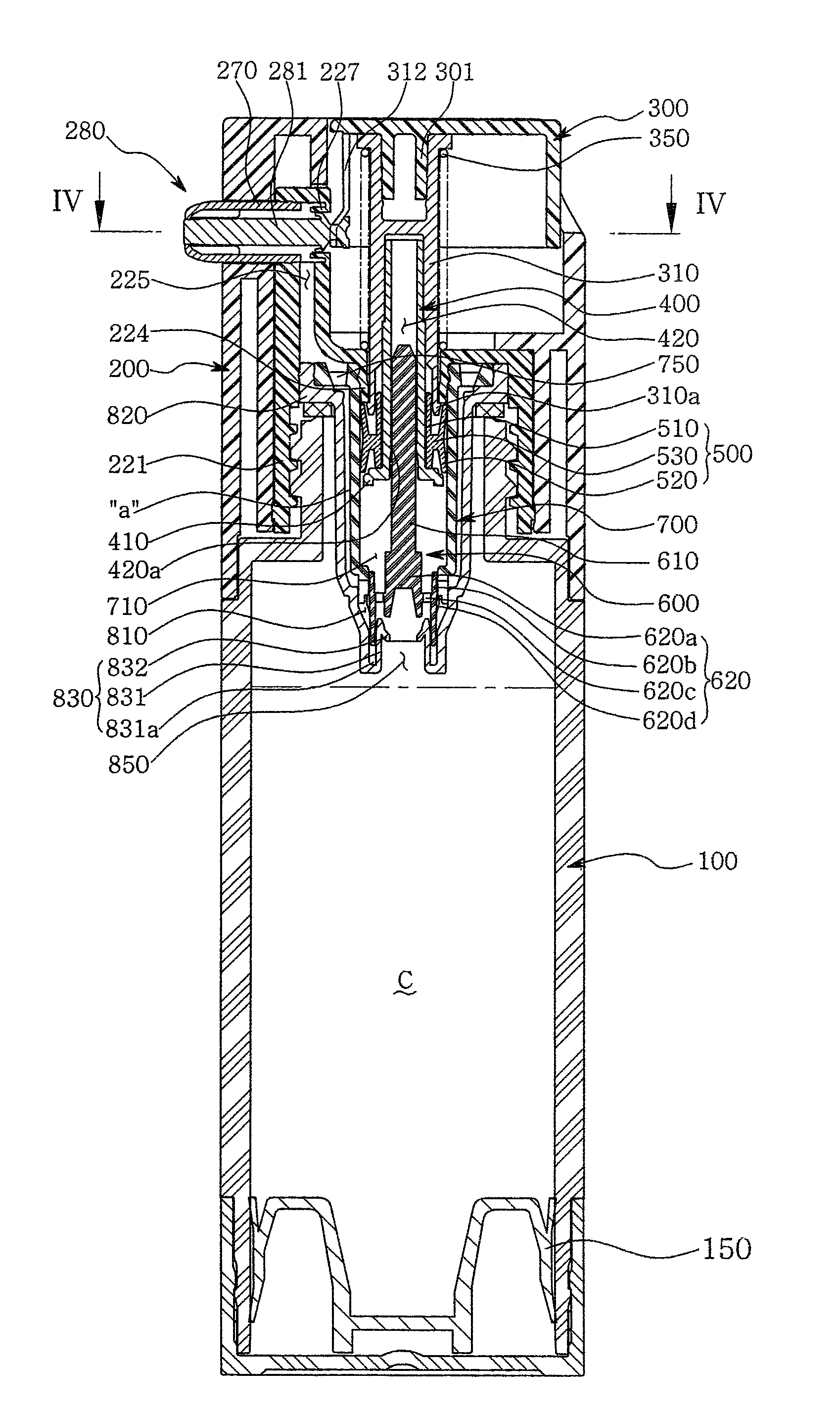
[0067]The present invention is characterized as follows. When a push button is moved upwards to suck a cosmetic, a piston, which is axially and movably coupled to an axial valve, primarily closes a guide passage defined between a cylinder and a cylinder bushing. When the axial valve is moved upwards in a state in which a cosmetic inlet port of the cylinder bushing is opened, the piston is secondarily moved upwards and sucks the cosmetic into the cylinder.

[0068]When the push button is pushed downwards to discharge the cosmetic, the axial valve primarily opens the guide passage defined between the cylinder and the cylinder bushing. When the axial valve is moved downwards in a state in which the cosmetic inlet port of the cylinder bushing is closed, the piston is secondarily moved downwards, thus compressing the cosmetic in the cylinder chamber and discharging the cosmetic from the cylinder chamber. Therefore, the cosmetics vessel of the present invention precisely realizes the operati...


PUM


Abstract

An airless type cosmetics vessel, in which, in order to suck a gel type cosmetic from a vessel body into a cylinder chamber, an axial valve primarily opens an inlet passage and closes an outlet passage according to stepwise upward movement of a piston and an axial valve, and the piston is further moved upwards, thus sucking the cosmetic into the cylinder chamber, and, in order to discharge the cosmetic from the cylinder chamber, the axial valve is primarily moved downwards so as to close the inlet passage and open the outlet passage, and the piston is further moved downwards, thus compressing the cosmetic in the cylinder chamber and discharging the cosmetic from the chamber, so that a precise cosmetic suction and discharge operation can be executed by the stepwise suction and discharge actions of the axial valve and the piston, separately provided, without malfunctioning.

Description

BACKGROUND OF THE INVENTION[0001]1. Field of the Invention[0002]The present invention relates, in general, to an airless type cosmetics vessel from which a cosmetic can be discharged by the action of pushing and releasing a push button.[0003]More particularly, the present invention relates to an airless type cosmetics vessel, from which can be discharged a cosmetic by the stepwise and continuous actions of a piston and an axial valve without any malfunctions thereof occurring during the discharge of the cosmetic from the vessel body, thus realizing reliability of a product, and which can be precisely operated while the cosmetic is being discharged because of the precise operation of a control nozzle, thus realizing operational precision and being convenient for users, and a discharge port of the nozzle of which can automatically be closed after the cosmetic has been discharged therefrom, thus preventing leakage of the cosmetic and allowing the users to safely carry the cosmetics ves...

Claims


Application Information

Patent Timeline
Patent Type & Authority Patents(United States)
IPC IPC(8): G01F11/00B67D7/58
CPCB05B11/3053A45D40/0075A45D2200/051B05B11/1053
Inventor BYEON, JAE SAM
Owner BYEON JAE SAM
Why Eureka
Try Eureka