
Light guide plate combination

A technology of light guide plate and shielding member, applied in the direction of light guide, optics, optical components, etc., can solve the problems of reducing the brightness of the light guide plate, light leakage of the light guide plate, affecting the light guide effect of the light guide plate, etc., so as to improve the light guide effect and improve the brightness. Effect

Inactive Publication Date: 2009-10-21
SHENZHEN FUTAIHONG PRECISION IND CO LTD
View PDF0 Cites 3 Cited by
  • Summary
  • Abstract
  • Description
  • Claims
  • Application Information

AI Technical Summary

Problems solved by technology

However, because the light guide plate is generally made of transparent materials, when the light emitted by the LED light source passes through the light guide plate, the light emitted by the LED light source will be guided by the surrounding wall of the light guide plate, that is, light leakage occurs in the light guide plate.
In addition, since the brightness of the light emitted by the LED light source is constant, the light guided by the surrounding wall of the light guide plate will inevitably reduce the brightness of the light transmitted by the light guide plate, thereby affecting the light guiding effect of the light guide plate.

Method used


Image

  • Light guide plate combination
  • Light guide plate combination

Examples


Embodiment Construction

[0009] The light guide plate assembly of the present invention is suitable for portable electronic devices such as mobile phones and personal digital assistants (PDAs).

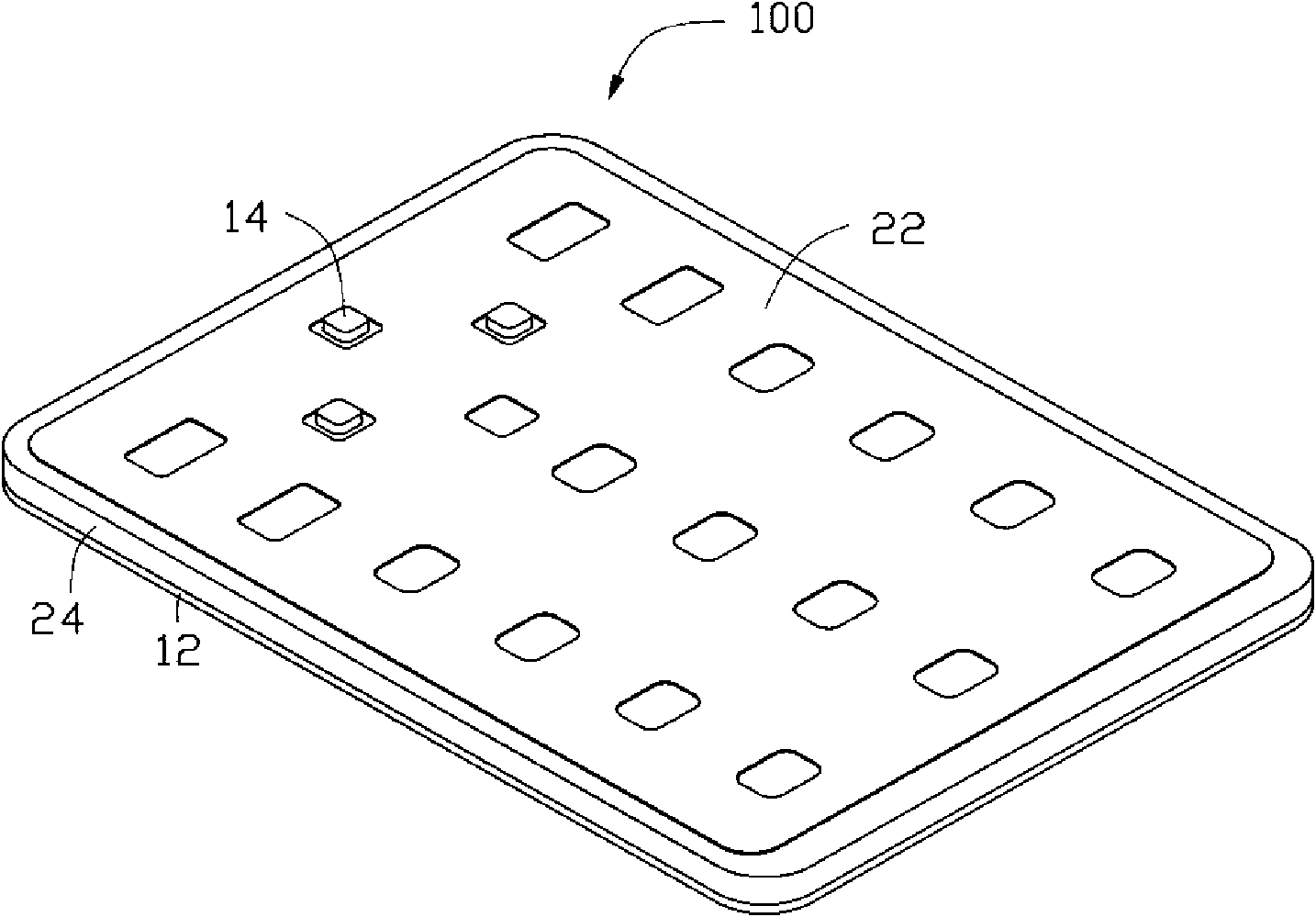
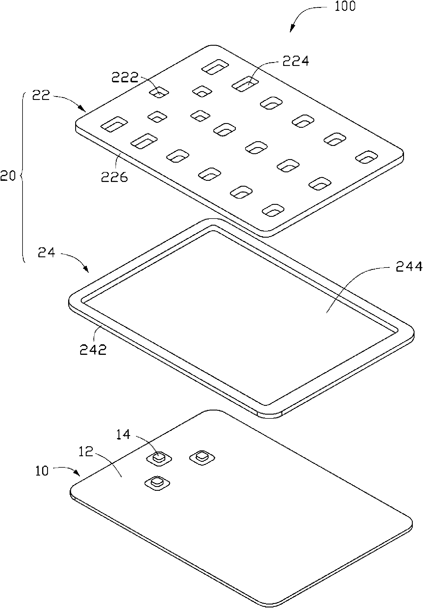
[0010] see figure 1 and figure 2 , the mobile phone 100 includes a circuit board 10 and a light guide plate assembly 20 . The light guide plate assembly 20 is disposed on the circuit board 10 .

[0011] The circuit board 10 is substantially a square plate, and includes a surface 12 facing the light guide plate assembly 20 . Several light sources 14 are arranged on the surface 12 . The light source 14 may be a light-emitting diode (light-emitting diode, LED for short). The light source 14 is accommodated in the light guide plate assembly 20, and the light emitted by the light source 14 is transmitted through the light guide plate assembly 20 to the place where the mobile phone 100 needs to be illuminated, such as the button (not shown) of the mobile phone 100. .

[0012] The light guide plate assembly 2...


PUM


Abstract

The invention provides a light guide plate combination, which comprises a light guide plate and a shadowing part comprising a framework; the framework surrounds a containing room; the light guide plate is contained in the containing room of the shadowing part; and the framework is formed on the periphery wall of the light guide plate.

Description

technical field [0001] The invention relates to a combination of light guide plates, in particular to a combination of light guide plates applied to portable electronic devices. Background technique [0002] In the design of mobile phones, in order to make them usable in the dark, the key lighting design of mobile phones is often used. Generally, light-emitting diodes (light-emitting diodes, hereinafter referred to as LEDs) are used as light sources, and the LEDs are placed on the PCB board of the mobile phone. Directly irradiate the desired light on the button number, so to make each button have a uniform brightness due to the illumination of the LED, the control of the number of LEDs will have different requirements depending on the design. Generally, a larger number of LEDs is required, which not only increases the cost, but also increases the overall power consumption of the mobile phone. In order to reduce the number and cost of LED light sources and obtain a uniform l...

Claims


Application Information

Patent Timeline
Patent Type & Authority Applications(China)
IPC IPC(8): G02B6/00H04M1/02
CPCG02B6/0068G02B6/0083G02B6/0073G02B6/0021
Inventor 曹金啼
Owner SHENZHEN FUTAIHONG PRECISION IND CO LTD
Learn More