Cutting edge gap back milling cutter numerical control machining method

A processing method and technology of back milling cutter, which is applied in metal processing equipment, milling machine equipment, program control, etc., can solve the problems of back milling cutter processing method without cutting edge space, unable to meet production requirements, time-consuming and laborious operation, etc. Achieve the effects of wide application range, guaranteed machining accuracy, and flexible input parameters

Inactive Publication Date: 2009-10-28
TIANJING UNIV OF TECH & EDUCATION
View PDF0 Cites 5 Cited by
  • Summary
  • Abstract
  • Description
  • Claims
  • Application Information

AI Technical Summary

Problems solved by technology

The most effective method is to use back milling cutter processing, but the current CAM software does not have a back milling cutter processing method specifically for cutting edge gap
However, the cutting edge gap program obtained by other methods often treats the cutting...

Method used


Image

  • Cutting edge gap back milling cutter numerical control machining method
  • Cutting edge gap back milling cutter numerical control machining method
  • Cutting edge gap back milling cutter numerical control machining method

Examples


Embodiment Construction

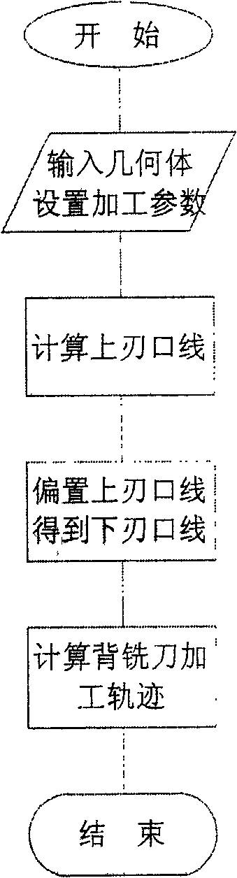
[0009] Such as figure 1 Shown: a CNC machining method of back milling cutter with cutting edge gap, which is carried out according to the following steps: (1) Input geometry, tool and set cutting edge height, final margin of cutting edge side, side margin of cutting edge gap, etc. Processing parameters; (2) Calculate the upper cutting edge line according to the profile allowance and the final allowance of the cutting edge side; (3) Offset the upper cutting edge line according to the cutting edge height to obtain the final lower cutting edge line; (4 ) The cutting edge line below is the back milling tool path for calculating the cutting edge gap based on the calculation of the cutting edge gap side allowance.

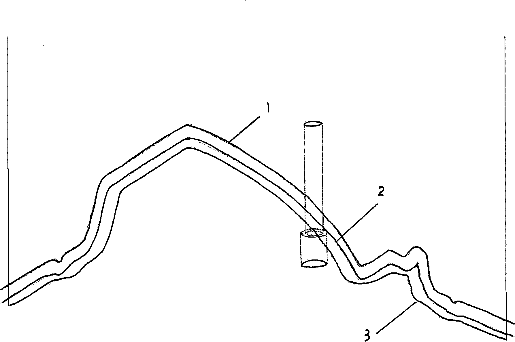
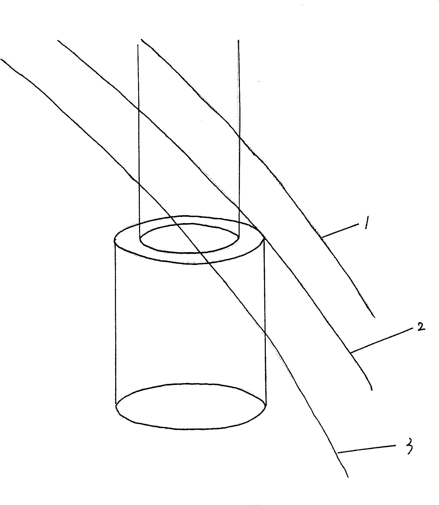
[0010] Such as figure 2 , 3 Shown: The gap of the cutting edge is generally processed by the back milling cutter, and the cyan surface is the trimming cutting edge. Compared with the sheet body, the solid body has the disadvantages of low precision, large amount of d...


PUM


Abstract

The invention discloses a cutting edge gap back milling cutter numerical control machining method, which comprises the following steps: (1) inputting a geometry and a cutter, and setting machining parameters; (2) calculating an upper cutting edge; (3) offsetting the cutting edge to obtain a final lower cutting edge; and (4) calculating a blade gap back milling cutter machining cutter path based on the lower cutting edge. The method has the advantages that: 1, the method provides the key for cutting edge gap back milling cutter numerical control machining, and ensures the normal height of the cutting edge so as to ensure the machining precision; 2, the method has simple operation, flexible parameter input and wide application range; and 3, when the cutter path is calculated, factors such as chuck interference, tool bit interference, corner deceleration, smoothening treatment on taper angles and the like are comprehensively considered, and the most reasonable cutter path is generated on the premise of safety. The invention finally realizes high-efficiency and precise cutting edge gap back milling cutter automatic numerical control machining.

Description

Technical field: [0001] The invention relates to a CAM processing method for cutting edge gap, in particular to a cutting edge gap processing method using a back milling cutter. Background technique: [0002] The trimming edge is a key part of the stamping die forming parts. In order to smoothly blank, there are generally dimensional requirements for the height of the edge. This needs to be guaranteed by processing methods. The most common method is to process the mold upside down from the reverse side, but this is not feasible for large molds. The most effective method is to use back milling cutter processing, but the current CAM software does not have a back milling cutter processing method specifically for cutting edge gap. However, the cutting edge gap program obtained by other methods often treats the cutting edge height as a geometric margin. This theoretical calculation error not only makes the operation time-consuming and laborious, but also has a large size deviati...

Claims


Application Information

Patent Timeline
IPC IPC(8): B23C3/12G05B19/4097
Inventor 蔡玉俊苗德华阎兵
Owner TIANJING UNIV OF TECH & EDUCATION
Why Eureka
Try Eureka