Device and method for pneumatic demoulding by injection molding of micro-fluidic chip

A microfluidic chip and injection molding technology, applied in the field of microfluidic chip injection molding pneumatic demolding devices and methods, can solve the problems of affecting the bonding quality, increase the rejection rate, uneven force, etc., and achieve smooth chip surface, Improve the pass rate and improve the effect of bonding quality

Inactive Publication Date: 2009-10-28
CENT SOUTH UNIV
View PDF0 Cites 5 Cited by
  • Summary
  • Abstract
  • Description
  • Claims
  • Application Information

AI Technical Summary

Problems solved by technology

[0002] At present, injection molding of microfluidic chips often adopts the method of ejector directly pushing the product out of the mold. During the demoulding process, ejection marks and stress cracks are easily produced on the surface, which affects the apparent quality of the chip. The phenomenon of uneven force will cause surface warping and deformation, which will affect the subsequent bonding quality and increase the scrap rate

Method used


Image

  • Device and method for pneumatic demoulding by injection molding of micro-fluidic chip
  • Device and method for pneumatic demoulding by injection molding of micro-fluidic chip

Examples


Embodiment 1

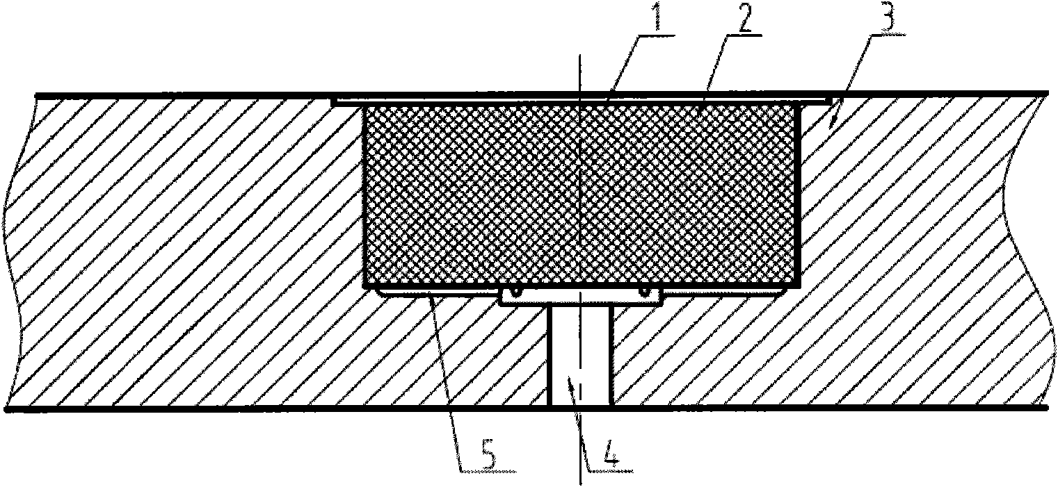
[0017] Such as figure 1 The schematic diagram of the structure of the pneumatic demoulding device and method shown, the demoulding structure includes a moving template 3, a cuboid moving mold insert 2 made of a gas-permeable material, a vent hole 4 connected to the bottom of the moving mold insert 2 and a radial Groove 5. The lower surface 1 of the cavity of the movable template 3 is provided with a mounting hole communicating with the cavity of the movable template, and the movable mold insert 2 is fixedly installed in the mounting hole, and has an interference fit with the mounting hole, and the movable mold insert 2 The end face is flush with the lower surface of the cavity of the movable template. The vent hole 4 is composed of two apertures of different sizes and is an integral structure. The radial groove 5 starts from the vent hole 4 and is radially distributed on the bottom of the installation hole opened on the lower surface 1 of the cavity of the movable template. T...

Embodiment 2

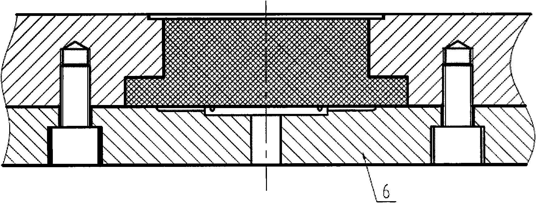
[0020] Such as figure 2 The demoulding structure shown is the embodiment 2 of the present invention. The difference from embodiment 1 is that the movable mold insert 2 made of air-permeable material is a stepped cuboid, and the movable template 3 and the movable mold are fixed by screw connection. The plate 6 is fixedly installed in the installation hole provided on the cavity lower surface 1 of the movable template 3 . In this embodiment, the movable mold insert 2 made of air-permeable material is easier to assemble and disassemble than in Embodiment 1.


PUM


Abstract

The invention provides a device and a method for conducting pneumatic demoulding of micro-fluidic chip by an air permeable material. The device comprises a movable die, an air permeable material and a movable die fixed plate; the lower surface of the cavity of the movable die is provided with an installation hole which is communicated with the cavity of the movable die; the installation hole is embedded with a movable die insert which is made of the air permeable material; and the bottom of the installation hole between the movable die insert and external compressed air source is provided with a venthole and a radial ditch that are used for circulating air. During the demoulding process, the compressed air is transmitted to the movable die insert made of the air permeable material uniformly by the radial ditch and enters a space between the formed chip and the movable die cavity by the movable die insert made of the air permeable material, thus ensuring the chip surface to bear uniform force during the demoulding process; furthermore, the warpage deformation generated in traditional demoulding mechanism does not occur to the device, the surface of the chip is smooth, the subsequent bonding quality is improved and the qualification rate is improved.

Description

technical field [0001] The invention relates to a device and method for pneumatically demoulding a microfluidic chip by using a gas permeable material. Background technique [0002] At present, injection molding of microfluidic chips often adopts the method of ejector directly pushing the product out of the mold. During the demoulding process, ejection marks and stress cracks are easily produced on the surface, which affects the apparent quality of the chip. The phenomenon of uneven force will cause surface warping and deformation, which will affect the subsequent bonding quality and increase the scrap rate. Contents of the invention [0003] The invention provides a demoulding device and method, which can eliminate ejection scars on the surface of chips, improve uneven stress in the demoulding process, and obtain chips with smooth surfaces. [0004] The invention relates to a device for pneumatically demolding a microfluidic chip by using a gas-permeable material, which ...

Claims


Application Information

Patent Timeline
IPC IPC(8): B29C45/40B29C45/26B29C45/34
Inventor 蒋炳炎申瑞霞翟瞻宇楚纯朋
Owner CENT SOUTH UNIV
Why Eureka
Try Eureka