Rubber-tyred container gantry crane automatic electricity getting system

A technology for container and gantry cranes is applied in the field of automatic power-taking systems for tire-mounted container gantry cranes, which can solve the problems of inability to automatically connect and disconnect safety slide lines and their tracks for power-taking, easy deviation, etc., so as to reduce maintenance workload, The effect of large access window and automatic ice, snow and frost removal

Inactive Publication Date: 2011-07-06
崔连涛 +1
View PDF1 Cites 0 Cited by
  • Summary
  • Abstract
  • Description
  • Claims
  • Application Information

AI Technical Summary

Problems solved by technology

The technology disclosed in the above-mentioned patent can realize the power supply function of the trolley installed on the sliding wire support, but the trolley cannot be separated from the sliding wire support. After entering the new storage yard, there must be a manual connection between the tire crane and the trolley on the sliding wire support
Therefore, this technology cannot automatically connect and disconnect from the safety slide line and its track to take power, because the tire crane cart is easy to go off when it is walking; in order to make the rubber-tyred container Automatic power-taking on the slide line, that is, the power-taking device of the tire crane is installed on the tire crane through the connecting mechanism, and the tire is hung on different power supply line sections of the safety slide line. ) and the control system, so as to realize automatic access to and departure from the safety slide line and its track.

Method used


Image

  • Rubber-tyred container gantry crane automatic electricity getting system
  • Rubber-tyred container gantry crane automatic electricity getting system
  • Rubber-tyred container gantry crane automatic electricity getting system

Examples


Embodiment Construction

[0027] The present invention will be further described in detail below in conjunction with the accompanying drawings and embodiments.

[0028] Such as Figure 1 to Figure 5 As shown, the description of the icon numbers is as follows:

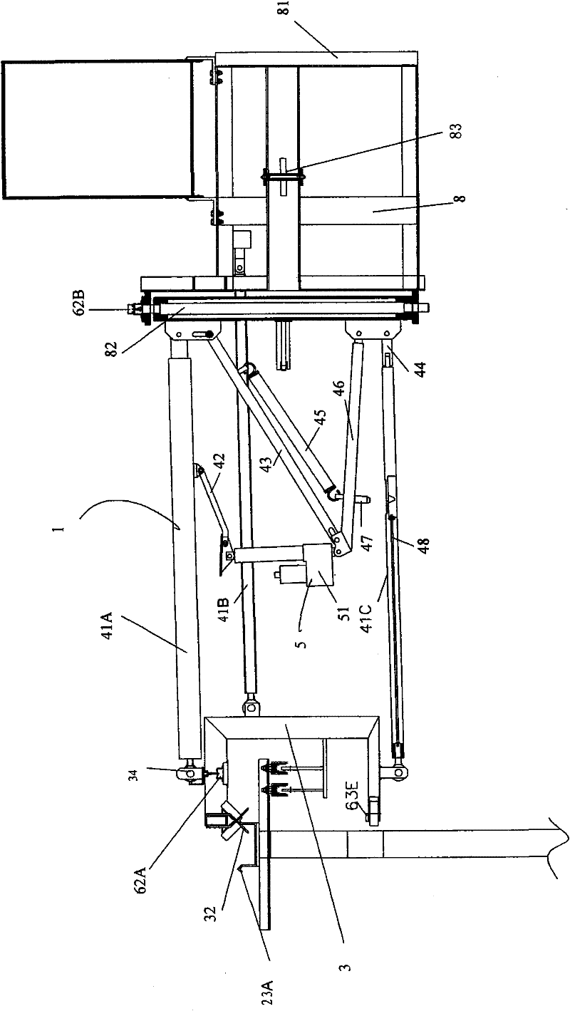
[0029] Electricity taking device 1, sliding wire track bracket 2, access / disengagement section 21, first track 23A, second track 23B, first detection board 24A, second detection board 24B, baffle plate 25, support column 26,

[0030] Power-taking section 22, first track 23A, second track 23B, power-taking end detection board 27, slide wire access locator 28,

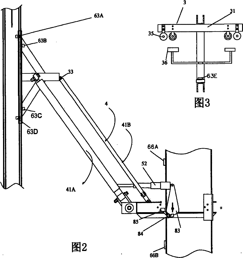
[0031] Power-taking trolley 3, main frame 31, track locator 32, elastic connector 33, joint bearing 34, walking wheels 35, power-taking brush 36,

[0032] Connection mechanism 4, first connecting rod 41A, second connecting rod 41B, third connecting rod 41C, floating connecting rod 42, pull rod 43, spring 45, support rod 46, pin 47, conversion joint 44, positioning connecting rod 48,

[...


PUM


Abstract

A rubber-tyred container gantry crane automatic electricity getting system comprises an electricity getting device and a slide wire track bracket that are controlled to act by a power system and a control system in a matching manner. The electricity getting device has an electricity getting trolley, a connecting mechanism and an electricity getting apparatus base. The slide wire track bracket hasan access / detachment section and an electricity getting section. The electricity getting trolley is composed of a main frame, a track locator, an elastic connector, an oscillating bearing, a travelling wheel and an electricity getting brush arranged on the trolley. The connecting mechanism comprises a first connecting bar, a second connecting bar, a third connecting bar, a floating connecting bar,a pull rod, a spring, a support bar, a pin, a transformation joint and a locating connecting bar. The electricity getting apparatus base comprises a base bracket, a main shaft, a horizontal rotary table, a locating pin and an electromagnet; the access / detachment section comprises a first track, a second track, a first detection plate, a second detection plate, a baffle and a supporting vertical post; and the connecting mechanism can lead the connection status of the electricity getting trolley and the electricity getting apparatus base to be switched between the access / detachment status and traction electricity getting status under the program control of the control system.

Description

technical field [0001] The invention relates to the technical field of gantry cranes, in particular to an automatic power-taking system for a tire-type container gantry crane. The tire type container gantry crane is referred to as "tyre crane" for short. Background technique [0002] In the prior art, there is application number 200610068525.4, application date 2006.08.19, publication number CN1915782A, name "Power Supply Device for Rubber-tyred Gantry Crane", which is provided with a sliding contact circuit on the fixed bracket, and the collector of the sliding contact circuit is fixed on a On the trolley where the trolley line moves in parallel, the lead-out line of the collector is connected to the electrical system of the rubber-tyred gantry crane, and the trolley is flexibly connected to the rubber-tyred gantry crane. The technology disclosed in the above-mentioned patent can realize the power supply function of the trolley installed on the sliding wire support, but th...

Claims


Application Information

Patent Timeline
Patent Type & Authority Patents(China)
IPC IPC(8): B66C13/12
Inventor 崔连涛赖琦波
Owner 崔连涛
Why Eureka
Try Eureka