Direct-drive composite type permanent magnet motor

A permanent magnet motor, composite technology, applied in electrical components, electromechanical devices, electric components, etc., can solve the problems of large installation space of motors and mechanical speed change devices, reducing system reliability and efficiency, and difficult to achieve high-precision control, etc. Achieve the effect of reducing maintenance workload and cost, compact structure and high power factor

Inactive Publication Date: 2008-12-24
许晓华
View PDF0 Cites 30 Cited by
  • Summary
  • Abstract
  • Description
  • Claims
  • Application Information

AI Technical Summary

Problems solved by technology

However, the daily maintenance of mechanical transmission components (such as gear box) and the replacement of wearing parts need to pay extra costs, and the cost of regular maintenance for long-distance operating systems (such as wind power generation, tidal power generation) will be extremely expensive ;The gap and friction loss between the mechanical transmission parts make it difficult to achieve high-precision control, which reduces the reliability and efficiency of the system and generates noise; the motor and the mechanical transmission device also require a large installation space

Method used


Image

  • Direct-drive composite type permanent magnet motor
  • Direct-drive composite type permanent magnet motor
  • Direct-drive composite type permanent magnet motor

Examples


Embodiment 1

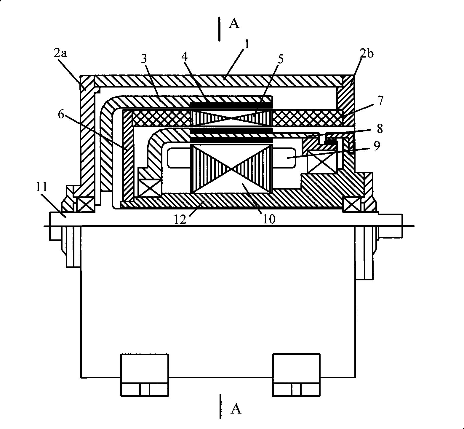
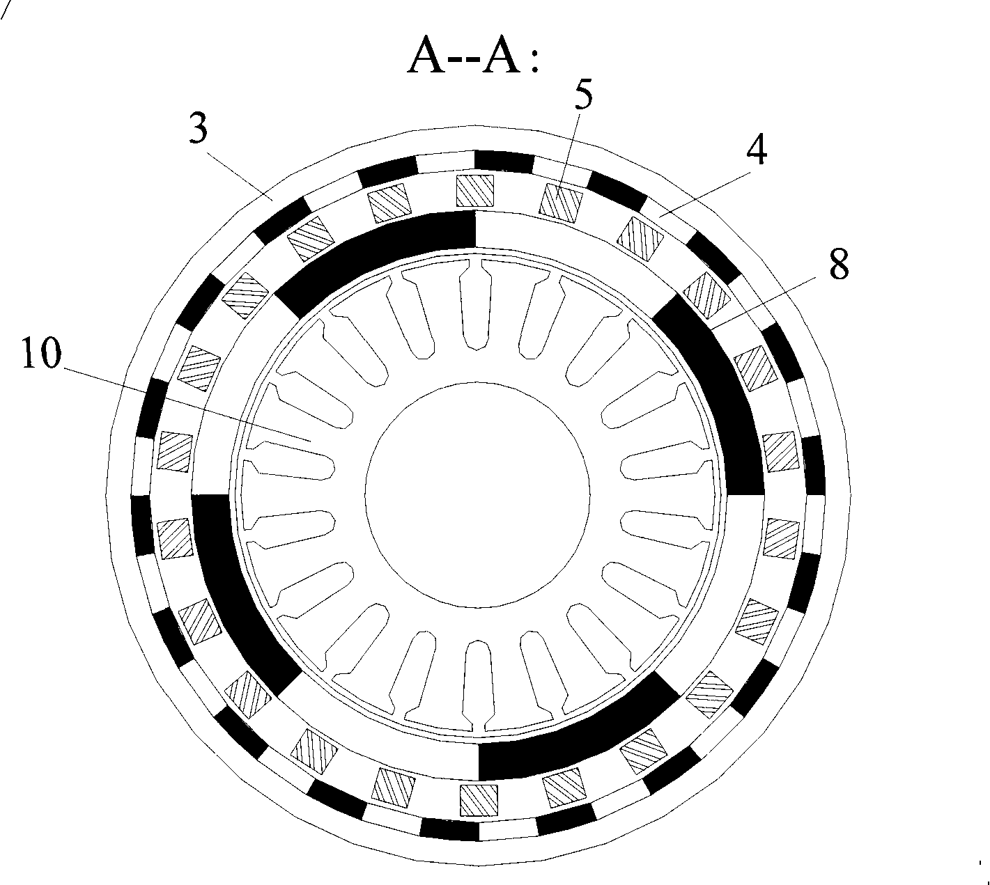
[0023] Embodiment one: see figure 1 and figure 2 , the direct drive compound permanent magnet motor includes a self-controlled permanent magnet motor and a concentric magnetic gear, the self-controlled permanent magnet motor and the concentric magnetic gear are combined into a double rotor structure, that is, the outer rotor 3 of the magnetic gear and the outer stator 7 and the inner rotor 8 and inner stator 12 of the permanent magnet motor adopt a sleeve-like structure to form a concentric structure.

[0024] The outer rotor 3 is a cup-shaped rotor, and its cup-shaped bottom is fixedly connected to the central rotating shaft 11; the outer stator 7 is a cylindrical body, one end of which is directly fixedly connected to an end cover 2b of the machine base 1, and the other end is fixed through a diameter The disc 6 is fixedly connected to the inner end of the inner stator 12; the inner rotor 8 is also a cup-shaped rotor, and its two ends are supported on the inner and outer e...

Embodiment 2

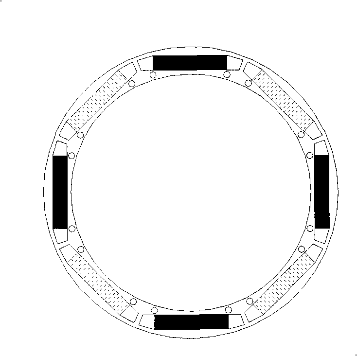
[0028] Embodiment two: see Figure 5 , direct drive This composite permanent magnet motor is made in axial series, which is equivalent to a self-controlled permanent magnet motor coaxially connected with a magnetic gear. The self-controlled permanent magnet motor is in the form of an inner rotor, that is, the inner rotor 8 in the above example is divided into two rotors: the self-controlled permanent magnet motor rotor 8a and the magnetic gear inner rotor 8b. The self-controlled permanent magnet motor rotor 8a has a large space. The form is more flexible, and it is easy to make a wide-speed adjustable permanent magnet motor.


PUM


Abstract

The invention relates to a direct-drive combined motor which comprises a self-control permanent-magnet motor and a concentric magnetic gear. The permanent-magnet motor and the magnetic gear are integrated by adopting the sleeve-type structure or the axial series connection structure. The combined permanent-magnet motor can automatically realize the high-speed low-torque power transfer and the low-speed high-torque power transfer therein without a mechanical gear case. The motor can serve as an electric motor and a power generator.

Description

technical field [0001] The invention relates to a motor, in particular to a direct-drive composite permanent magnet motor suitable for low speed and high torque. Background technique [0002] A traditional motor drive system is a combination of an electric motor and a mechanical transmission mechanism. However, the daily maintenance of mechanical transmission components (such as gear box) and the replacement of wearing parts need to pay extra costs, and the cost of regular maintenance for long-distance operating systems (such as wind power generation, tidal power generation) will be extremely expensive ; The gap and friction loss between the mechanical transmission parts make it difficult to achieve high-precision control, which reduces the reliability and efficiency of the system and generates noise; the motor and the mechanical transmission device also require a large installation space. Contents of the invention [0003] The object of the present invention is to provid...

Claims


Application Information

Patent Timeline
Patent Type & Authority Applications(China)
IPC IPC(8): H02K7/00H02K16/00H02K1/27H02K3/12
CPCH02K16/00H02K16/02H02K51/00
Inventor 章跃进江建中崔巍杜世勤刘新华龚宇汪信尧
Owner 许晓华
Why Eureka
Try Eureka