
Heavy hydraulic walking chassis

A walking chassis and walking-type technology, which is applied to drilling equipment, drilling equipment and methods, and earthwork drilling and production, and can solve the problems of increasing the supporting surface of equipment and not exceeding the width

Inactive Publication Date: 2009-10-28
王来朋
View PDF0 Cites 11 Cited by
  • Summary
  • Abstract
  • Description
  • Claims
  • Application Information

AI Technical Summary

Problems solved by technology

The heavy-duty hydraulic walking chassis adopts a detachable double-boat side shoe structure to solve the problems of increasing the supporting surface of the equipment and not exceeding the width during transportation.

Method used


Image

  • Heavy hydraulic walking chassis

Examples


Embodiment Construction

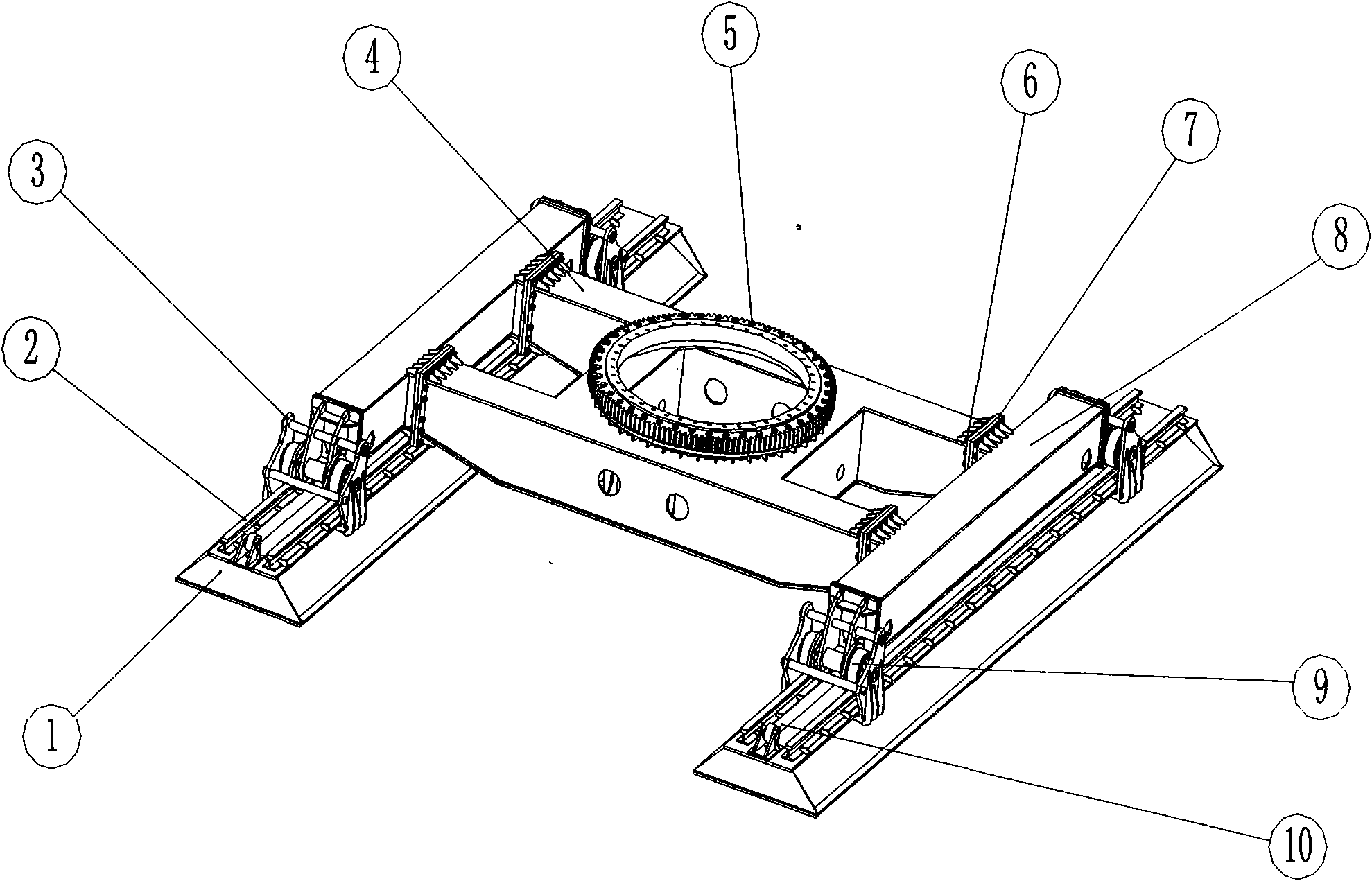
[0007] The chassis is mainly used in large-scale long auger drilling machines as an important structure for loading and transportation, supporting travel and rotary positioning. When loading the vehicle, in order to reduce the loading width, remove the connecting fastener ⑥ to separate the H-shaped beam ④ from the supporting beam ⑧ of the trolley. The parts ①②③⑧⑨⑩ can be transported in bulk, while the H-shaped beam and the upper part of the equipment can be transported in bulk. Transport together so that the chassis section does not exceed the transport width. In order to increase the grounding area during construction, the H-shaped girder ④ and the trolley support beam ⑧ are butted through the connecting flange ⑦, and then connected with the connecting fastener ⑥. After installing parts ①②③⑨⑩ and other parts, the grounding area and supporting span of the chassis of the whole machine can be increased. When walking in a straight line during the construction process, the hydrau...


PUM


Abstract

The invention relates to a heavy hydraulic walking chassis capable of being used in pile-driving machinery. The heavy hydraulic walking chassis has a dismountable double ship-shaped side boot (1) structure, wherein the middle of a ship-shaped side boot is provided with a trolley track (2) and a walking trolley (9), and an H-shaped girder (4) realizes linear reciprocating movement by the connection of a walking oil cylinder (10) and is provided with a rotary bearing (5) to realize the relative rotary motion with an upper-part stand. The invention favorably solves the problems of linear reciprocating motion, relative rotation and stability and transportation width exceedance of large-scale pile-driving equipment in construction, has simple structure and is easy to manufacture.

Description

technical field [0001] The invention relates to a walking chassis of mechanical equipment, in particular to a detachable heavy-duty hydraulic walking chassis suitable for piling mechanical equipment. technical background [0002] Pile machinery and equipment are mostly used in field construction, and the environment of the work site is complex. However, the large-scale pile driver equipment has a large shape and a high center of gravity. It is necessary to ensure the stability of the equipment during construction, and the whole machine has a small grounding specific pressure to the ground. For this reason It requires the chassis to have a larger grounding area, thereby improving the stability of the whole machine and reducing the grounding specific pressure. In addition, the construction site changes frequently, and the ultra-wide limit should be considered when the equipment is transferred. The chassis should not only meet the construction stability, but also meet the ultra...

Claims


Application Information

Patent Timeline
Patent Type & Authority Applications(China)
IPC IPC(8): E21B7/02E21B15/00
Inventor 王来朋
Owner 王来朋
Learn More