Eureka AIR delivers breakthrough ideas for toughest innovation challenges, trusted by R&D personnel around the world.

Blade capable of weakening shock strength of transonic speed turbine

A technology of shock wave intensity and transonic speed, which is applied in the direction of blade support components, engine components, machines/engines, etc., can solve the unstable flow field of the cascade flow field of the turbine engine, weaken the shock wave intensity of the transonic turbine, and the turbine engine Noise and other problems, to achieve the effect of weakening transmission, stable flow, and noise reduction

Inactive Publication Date: 2009-10-28
HARBIN INST OF TECH
View PDF0 Cites 4 Cited by
  • Summary
  • Abstract
  • Description
  • Claims
  • Application Information

AI Technical Summary

Problems solved by technology

[0003] In order to solve the problems of strong shock wave in the cascade flow field of a transonic air-cooled turbine, the shock wave makes the flow field of the cascade of the turbine engine unstable and the noise of the turbine engine is large, the present invention proposes a Blades of Turbine Shock Strength

Method used


Image

  • Blade capable of weakening shock strength of transonic speed turbine
  • Blade capable of weakening shock strength of transonic speed turbine
  • Blade capable of weakening shock strength of transonic speed turbine

Examples


specific Embodiment approach 1

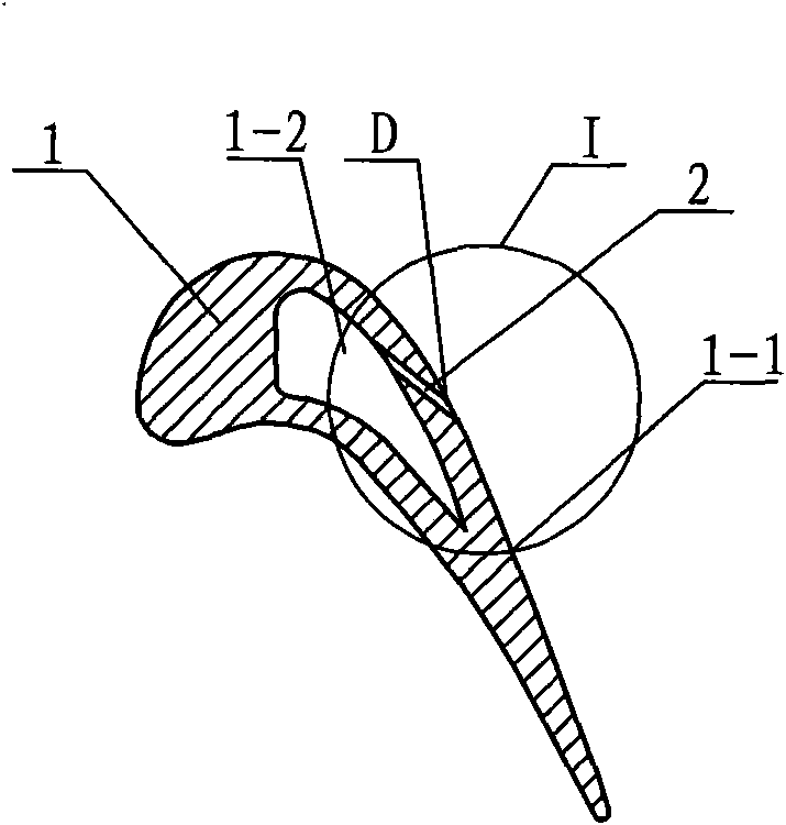
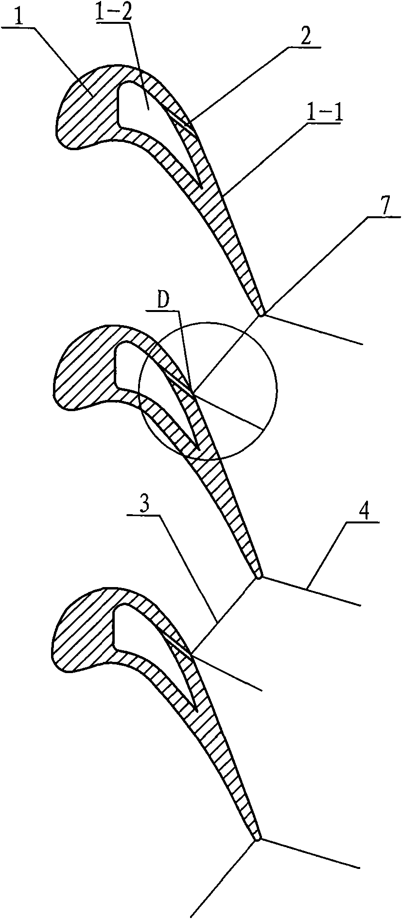
[0007] Specific implementation mode one: combine figure 1 and figure 2 To illustrate this embodiment, at least one cold air injection hole 2 communicating with the inner cavity 1-2 is provided on the shock refraction ray formed by the combination of shock refraction points on the suction surface 1-1 of the blade 1 in this embodiment. The air flow from the compressor enters the blade flow field through the cold air nozzle 2 from the inner cavity, forming a cold air jet, which changes the local pressure difference in the propagation direction of the shock wave pressure surface branch at the trailing edge 7, and weakens the shock wave pressure surface branch 3 and the propagation strength of branch 4 of the suction surface, as image 3 As shown, the shock wave strength of the transonic turbine is weakened, the flow of the cascade flow field is significantly improved, and the energy loss is reduced.

specific Embodiment approach 2

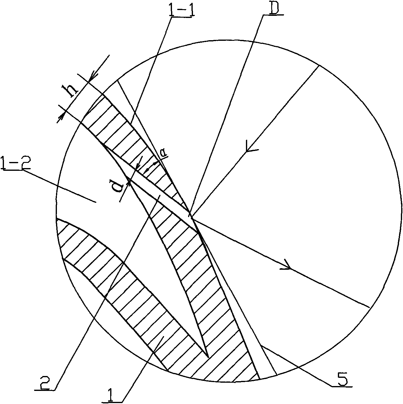
[0008] Specific implementation mode two: combination figure 2 The present embodiment will be described. The included angle α between the cold air injection hole 2 and the tangent 5 of the suction surface in this embodiment is 20°-160°. The size of the included angle α can be adjusted according to the incident direction of the shock wave.

specific Embodiment approach 3

[0009] Specific implementation mode three: combination figure 2 The present embodiment will be described. The diameter d of the cool air injection hole 2 in the present embodiment is 0.1 to 5 times the thickness h of the blade wall surface. The diameter of the cold air injection hole 2 can be changed according to the magnitude of the shock wave intensity.


PUM


Abstract

A blade capable of weakening shock strength of a transonic speed turbine relates to a blade and aims at solving the problem that the strong shock existing in a blade cascade flow field of a transonic speed air cooling turbine causes the unstable flow of the blade cascade flow field of the turbine engine and high noise of the turbine engine. A shock refracted ray combined by shock wave refraction points on a suction surface of the blade is provided with at least one cold air jet orifice communicated with an inner cavity. The blade conducts cold air jet through the cold air jet orifice, thus changing the pressure distribution in a transonic speed turbine stage blade cascade flow passage, namely after injecting cold air with relatively high pressure, increasing the local pressure value of fluid behind throat, weakening the development of expansion wave of a stationary blade cascade expansion section and further controlling the strength of strong compressional wave induced by the expansion; and simultaneously, the cold air jet on a shock propagation passage weakens the local pressure difference and the propagation of shock wave toward the suction surface, thus leading the flow of the blade cascade flow field to be more stable and reducing the noise of the turbine engine.

Description

technical field [0001] The invention relates to a blade. Background technique [0002] A shock wave is a collection of strongly compressed gas waves existing in a supersonic flow, and it is a strongly compressed beam. In ideal flow, it has no width. But in the actual flow, the shock wave has thickness due to the viscosity of the gas. The shock wave is a strong discontinuity in the cascade flow field. The temperature, pressure, and density of the gas passing through it suddenly increase, and the flow velocity suddenly decreases, which makes the flow field of the cascade flow unstable and affects the stability of the turbine engine. make an impact. Shock waves are also the culprit of engine noise, and strong shock waves hit the blades to produce a harsh buzzing sound. Therefore, controlling the shock wave structure and intensity plays a very important role in the turbine engine. Contents of the invention [0003] In order to solve the problems of strong shock wave in th...

Claims


Application Information

Patent Timeline
Patent Type & Authority Applications(China)
IPC IPC(8): F01D5/18
Inventor 王凯王松涛
Owner HARBIN INST OF TECH
Why Eureka
Eureka Blog
Learn More