Automatic flow control water-saving valve

A water-saving valve and valve body technology, applied to valve details, safety valves, balance valves, etc., can solve problems such as blockage, high production costs, troublesome maintenance and replacement of parts or accessories, and achieve convenient use and structural Simple, low-cost effect

Inactive Publication Date: 2009-10-28
陈劲松
View PDF0 Cites 4 Cited by
  • Summary
  • Abstract
  • Description
  • Claims
  • Application Information

AI Technical Summary

Problems solved by technology

[0002] At present, the water-saving valve that automatically adjusts the flow area through the water pressure and elastic device to realize the purpose of automatically controlling the water flow has a complex structure and many related parts or accessories, and the production cost is high; the parts or accessories It is troublesome to maintain and replace, and once damaged, it will affect the overall service life of the product; at the same time, due to the complex structure, it is easy to be blocked by scale and foreign objects in the water, affecting normal water use

Method used


Image

  • Automatic flow control water-saving valve
  • Automatic flow control water-saving valve
  • Automatic flow control water-saving valve

Examples


Embodiment 1

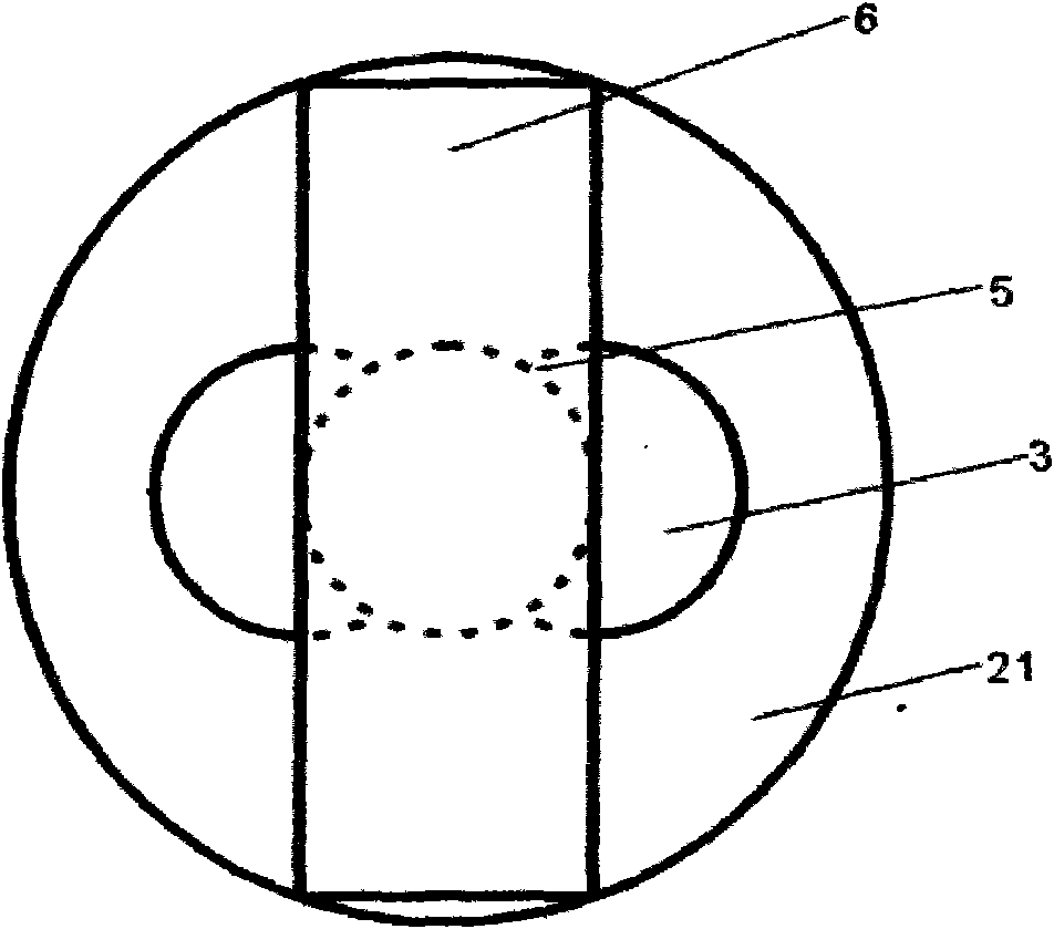
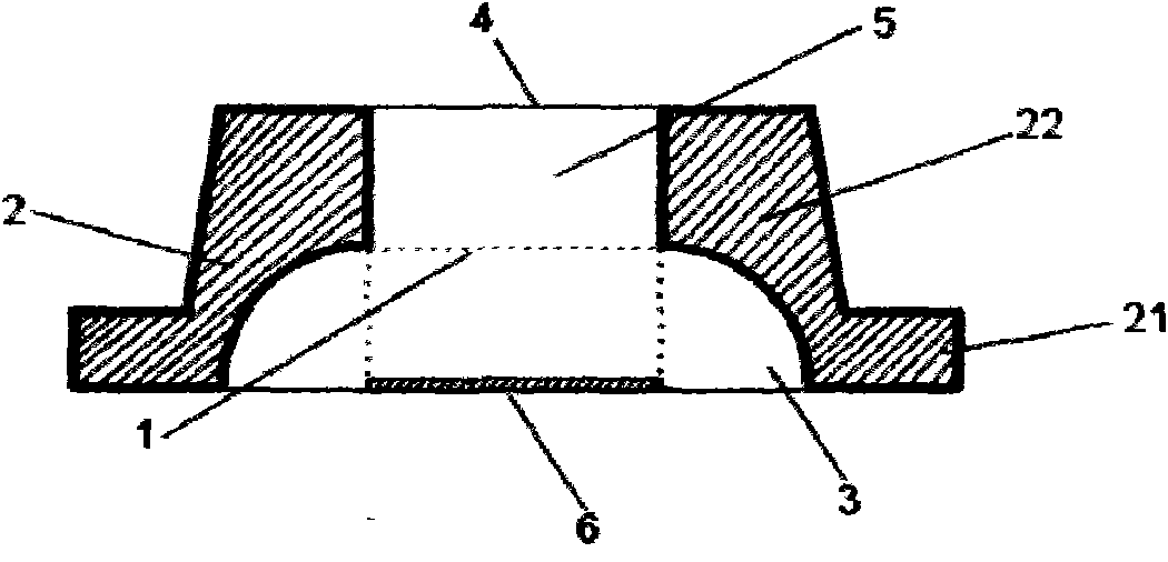
[0018] Embodiment one: if figure 1 , 2 and 3. The automatic flow control water saving valve of the present invention comprises a valve body 2 and an elastic baffle 6 . The valve body 2 is integrally cast, and the outer contour of the valve body 2 is "convex" protruding outwards. There is a cylindrical water inlet channel 5 longitudinally in the middle of the valve body 2. The valve body 2 includes a round table clamping section 22, which is also a water outlet section. The optimal shape of the clamping section 22 is narrow at the top and wide at the bottom. The water inlet channel 5 extends vertically to the top of the valve body 2. The bottom surface of the clamping section 22 forms a circle, and then the circle formed by the bottom surface of the clamping section 22 is the center. Dig out 2 quarter spheres (when the thickness of the clamping section 22 is not enough, the sphere may exceed the water outlet section) with the same radius at the clamping section 22, thus formi...

Embodiment 2

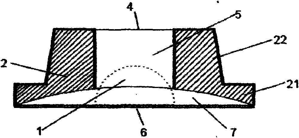
[0021] Embodiment two: if figure 1 , Figure 5 , as shown in Figure 6. The difference from Embodiment 1 is that the bottom of the valve body 2 is not a plane, but a suitable raised spherical surface. In this case, the bottom of the limiting groove 7 is a plane, and the corresponding baffle is an arcuate baffle. The rest are the same as the first embodiment.

Embodiment 3

[0022] Embodiment 3: Under the same conditions as in Embodiment 1 and Embodiment 2, when the elasticity of the elastic baffle plate is zero, that is, it has no elasticity, it can also achieve a considerable throttling effect. The opening size of the nozzle is used to realize the quantitative control flow. At this time, it is not necessary to provide a limiting groove on the valve body, but to provide a water inlet channel laterally at the corresponding position.


PUM


Abstract

The invention discloses an automatic flow control water-saving valve, which comprises a valve body with a raised external contour taking the shape of 'tu' (Chinese character); the valve body is vertically provided with a cavity channel communicating a water inlet and a water outlet; a flexible baffle with at least one part covering the water inlet is arranged below the water inlet at certain interval; a clearance between the flexible baffle and the water inlet is step-like; the water inlet is at the smaller end; a lateral water inlet clearance is formed between the flexible baffle and the water inlet; a limiting slot is arranged above and matched with the flexible baffle; a raised blocking column or frustum of a cone or multidimensional frustum of a prism is upwards arranged on the valve body. The water-saving valve compresses the water entering area of the water inlet channel by the deformation of the flexible baffle when a set water pressure is exceeded, thereby reducing flow and realizing the purpose of saving water. The valve body adopts integrated casting and has simple structure, convenient use and low cost.

Description

technical field [0001] The invention relates to a throttling valve device, in particular to a water-saving valve which can automatically control the water flow according to the water pressure of the water source and basically does not affect the water comfort. Background technique [0002] At present, the water-saving valve that automatically adjusts the flow area through the water pressure and elastic device to realize the purpose of automatically controlling the water flow has a complex structure and many related parts or accessories, and the production cost is high; the parts or accessories It is troublesome to maintain and replace, and once damaged, it will affect the overall service life of the product; at the same time, due to the complex structure, it is easy to be blocked by scale and foreign objects in the water, affecting normal water use. Contents of the invention [0003] In view of the above deficiencies, the present invention provides an automatic flow contro...

Claims


Application Information

Patent Timeline
Patent Type & Authority Applications(China)
IPC IPC(8): F16K17/36F16K27/00
Inventor 陈劲松
Owner 陈劲松
Why Eureka
Try Eureka