Method for regulating image quality control parameter of optical indicator

A technology for indicating device and image quality, applied in the input/output process of data processing, electrical digital data processing, instruments, etc., can solve problems such as operation errors and abnormal mouse movement, and achieve the effect of solving operation errors.

Inactive Publication Date: 2012-03-28
APEXONE MICROELECTRONICS SHANGHAI +1
View PDF3 Cites 0 Cited by
  • Summary
  • Abstract
  • Description
  • Claims
  • Application Information

AI Technical Summary

Problems solved by technology

[0007] The present invention proposes a method for adjusting image quality control parameters of an optical pointing device, which is used to overcome the defects in the prior art that only by adjusting the image exposure through the average pixel value, there will be an operation error, resulting in abnormal mouse movement

Method used


Image

  • Method for regulating image quality control parameter of optical indicator
  • Method for regulating image quality control parameter of optical indicator
  • Method for regulating image quality control parameter of optical indicator

Examples


Embodiment approach

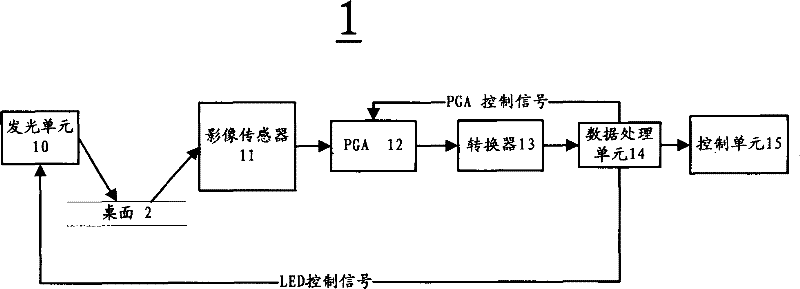
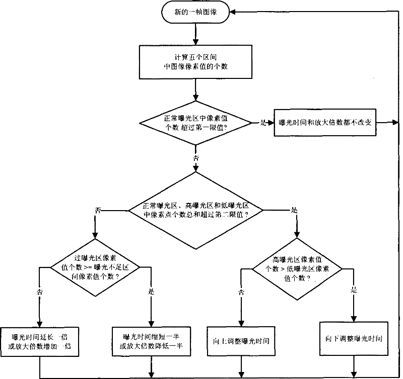
[0025] see figure 2 As shown, it is a flowchart for implementing the method for adjusting the image quality control parameters of the optical pointing device of the present invention. In the present invention, the image quality control parameters include light source exposure time and programmable gain amplifier multiples, and this method is applied to computer or video systems On the optical indicator device, the indicator device is provided with an image sensor, and the image sensor has a plurality of sensing units, and the plurality of sensing units are used to sample (or photograph) a surface according to the exposure parameter value image, this method mainly includes the following steps:

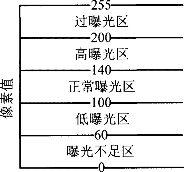
[0026] According to the image pixel values ​​from small to large, five pixel value distribution areas are established in order of underexposure area, low exposure area, normal exposure area, high exposure area and over exposure area. For the values ​​of each pixel value distribution ar...


PUM


Abstract

A method for regulating an image quality control parameter of an optical indicator comprises the steps of: establishing five pixel value distributing regions of an underexposure region, a low exposureregion, a normal exposure region, a high exposure region and an overexposure region according to the image pixel value from small to large; obtaining a frame image of the surface by an image sensor of the indicator; calculating the pixel value of each pixel point of the frame image; counting the numbers of the pixel points of the image on each exposure region; retaining the prior image quality control parameter if the number of the pixel points in the normal exposure region exceeds a first limit value; regulating the exposure time of the light source according to the relationship of the numbers of pixel points in the high exposure region and the low exposure region if the amount of pixel points in the normal exposure region fails to exceed the first limit value, while the sum of the numbers of the pixel points in the normal exposure region, the high exposure region and the low exposure region exceeds the second limit value; and vice versa, regulating the image quality control parameter by a second method.

Description

【Technical field】 [0001] The invention relates to an image quality control method, in particular to a method for adjusting image quality control parameters used on an optical pointing device of a computer or video system. 【Background technique】 [0002] figure 1 It is a block diagram of a photoelectric mouse, the mouse 1 includes a light source or light emitting unit (LED) 10, an image sensor 11, a programmable gain amplifier (PGA) 12, a converter (A / D) 13, a data processing unit 14 and a control unit 15 , during work, the light emitting unit 10 is usually lit at a certain frequency, and emits light onto the desktop 2 on which the mouse 1 is placed. Usually, the desktop 2 has certain texture features, that is, a microscopic uneven surface. The light emitting unit 10 The emitted light is reflected by the desktop 2, and is focused by a lens (not shown) before being input to the image sensor 11. The image sensor 11 forms a voltage or current signal according to the intensity o...

Claims


Application Information

Patent Timeline
Patent Type & Authority Patents(China)
IPC IPC(8): G06F3/033
Inventor 肖勇邵菊花谢承华
Owner APEXONE MICROELECTRONICS SHANGHAI
Why Eureka
Try Eureka