Connector

A connector and connecting terminal technology, applied in the direction of connection, two-part connecting device, and components of connecting device, etc., can solve the problems of excessive load on connecting terminal, excessive rotation of rotating operation, plastic deformation of connecting terminal, etc. Improved accuracy, improved positioning accuracy, and the effect of preventing plastic deformation

Inactive Publication Date: 2009-10-28
ORMON CORP
View PDF1 Cites 1 Cited by
  • Summary
  • Abstract
  • Description
  • Claims
  • Application Information

AI Technical Summary

Problems solved by technology

[0004] However, in the above-mentioned connector, as in Patent Document 1 image 3 As shown in FIG. 4 , when the operation member 20, that is, the operation lever, is locked, the rotation operation will cause excessive rotation.
Therefore, the operating rod is lifted due to the principle of leverage, and it is easy to fall off from the housing, that is, the base
[0005] In addition, when the operation lever comes off, an excessive load acts on the contact point, that is, the connecting terminal, so that the connecting terminal is plastically deformed and there is a problem that connection cannot be performed.

Method used


Image

  • Connector
  • Connector
  • Connector

Examples


Embodiment Construction

[0064] Next, an embodiment of the present invention will be described with reference to FIGS. 1 to 13 .

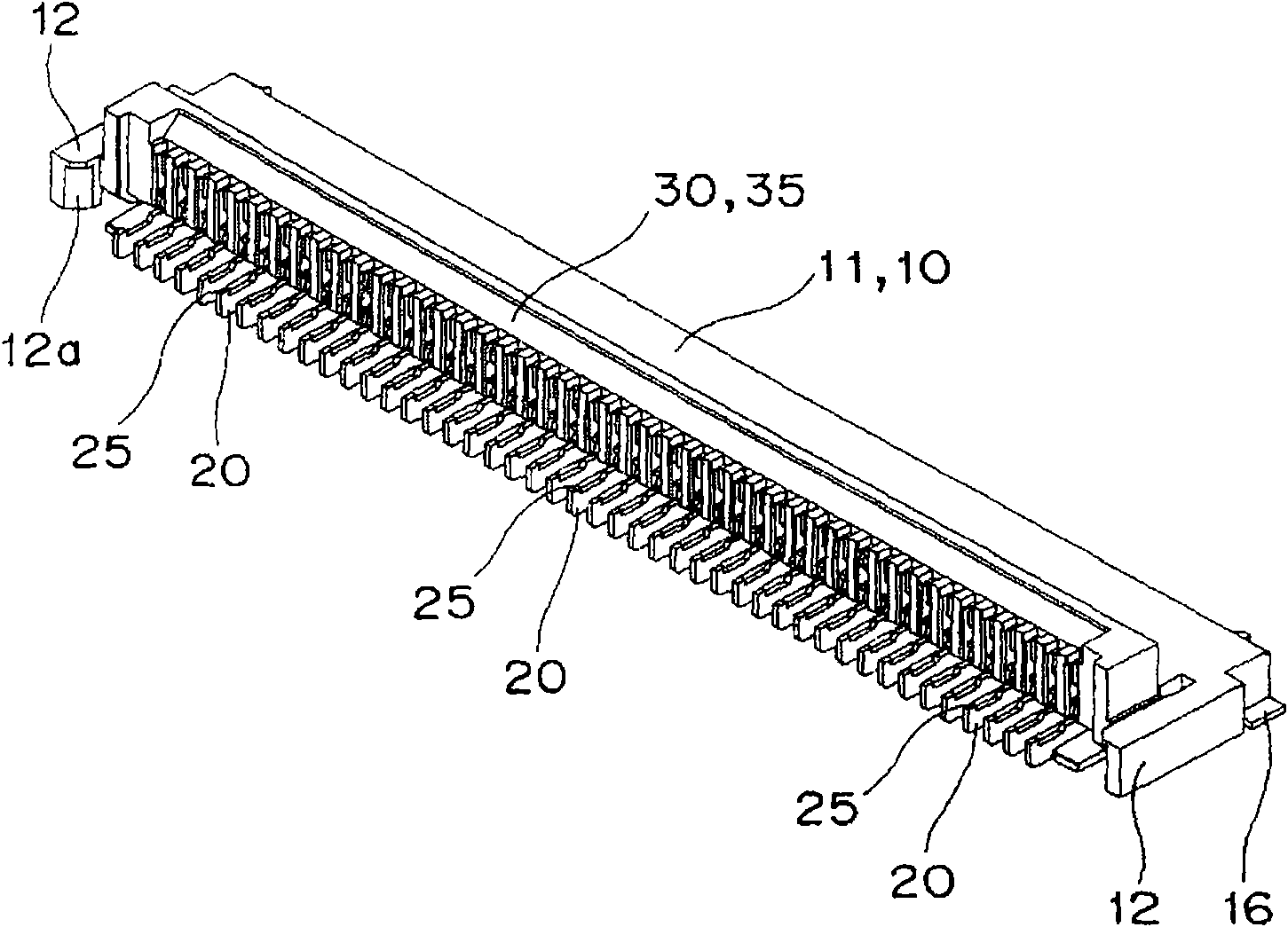
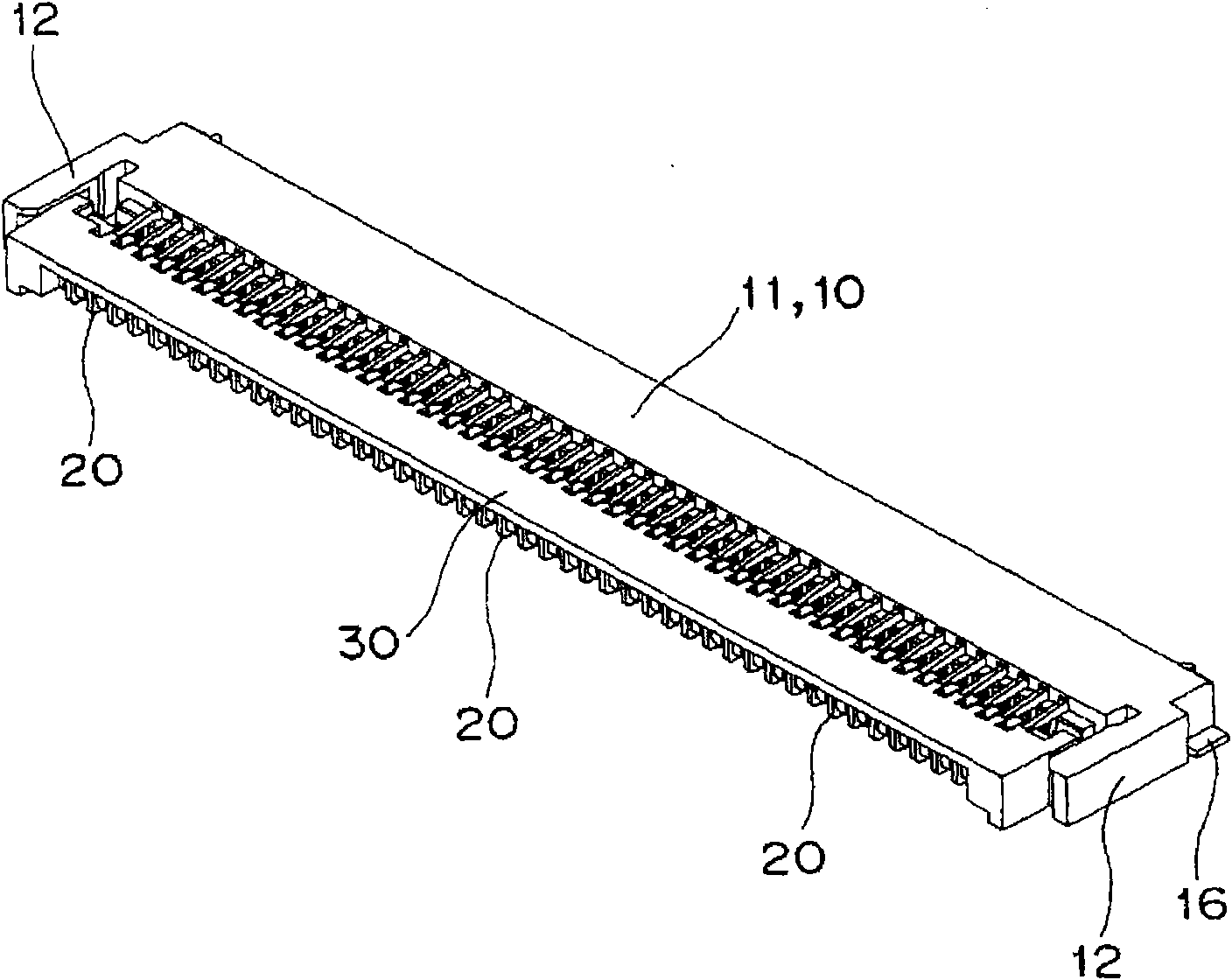
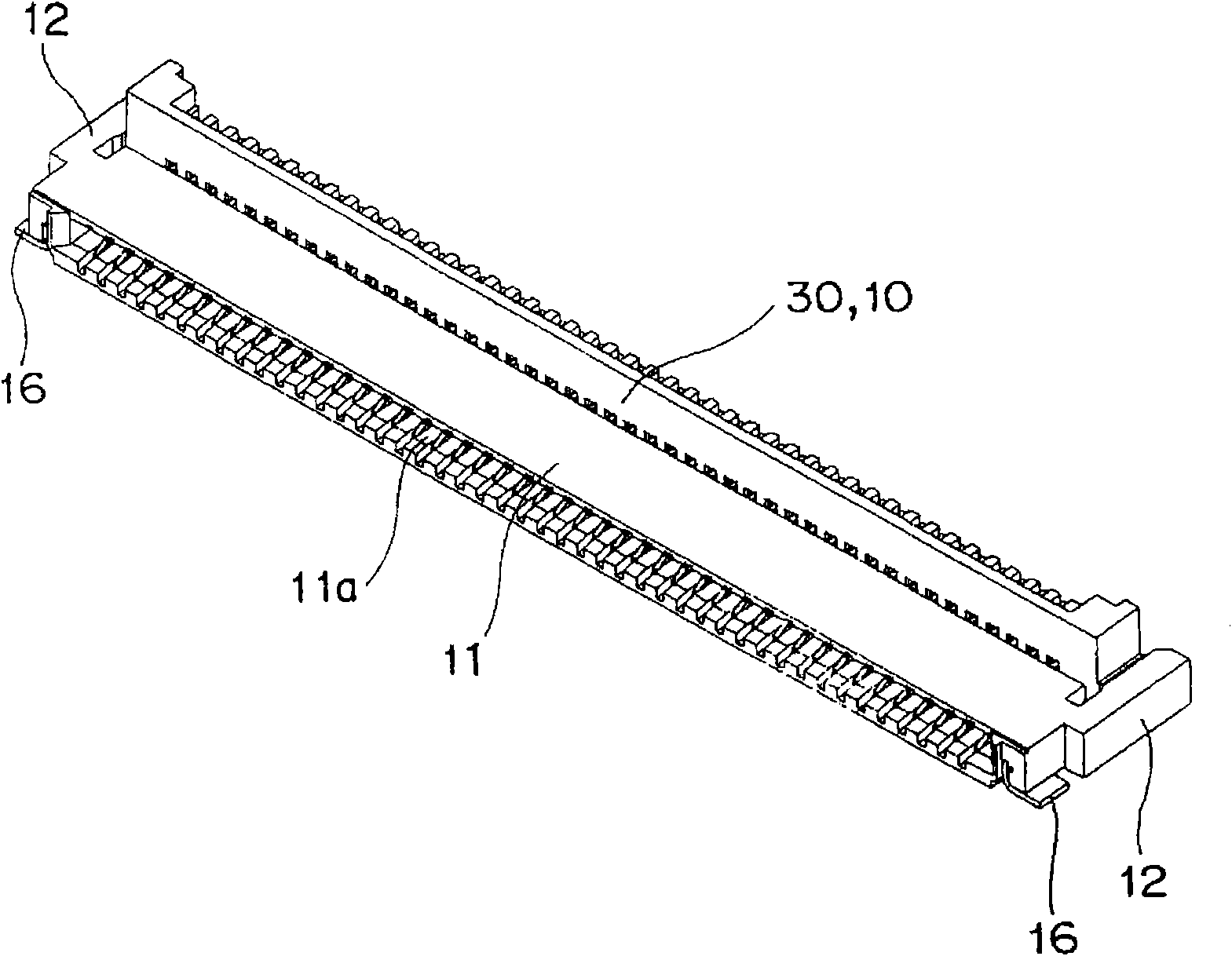
[0065] Figure 1~ image 3 As shown, the connector 10 of the first embodiment is roughly composed of a base 11, a connection terminal 20, and an operating lever 30, and is detachably connected to a flexible printed circuit board (FPC) 40 (FIGS. 4 and 5).

[0066] As shown in Figure 6 (A) and (B), the base 11 respectively extends from one side edge of the end surface of both sides to the back side in parallel with elastic arms 12, 12, and is arranged side by side with a predetermined interval. Through the insertion hole 13 on the front.

[0067] In addition, as shown in FIG. 6(A), on the inward surface of the elastic arm portion 12, a guiding tapered surface 12a is formed on the front edge thereof, and a shaft support portion 12b is formed on the inner side thereof. In addition, the base 11 extends a guide plate 14 from the lower edge of the back side between the elastic ar...


PUM


Abstract

A connector to be surface mounted on a wiring board has a base having an opening to be inserted with a tip portion of a flexible printed circuit board at a front surface, and having a plurality of insertion holes passing from the front surface to a rear surface juxtaposed at a predetermined pitch, a connection terminal arranged in a projecting manner with a substantially T-shaped operating piece having at one end a movable contacting point that comes into pressure contact with joints juxtaposed at the tip portion of the flexible printed circuit board, the connection terminal having one end that becomes a fixed contacting point inserted to the insertion hole from the rear surface side, and an operating lever in which a cam portion is fitted into a turning recessed portion arranged at an upper side of the connection terminal to act as a turning supporting point, the cam portion driving an operation receiving portion positioned at the other end of the operating piece. A position regulation contacting portion that contacts a position regulating portion arranged at the upper side of the connection terminal when the operating lever is turned and a locking operation is completed is arranged at a lower surface of the operating lever.

Description

technical field [0001] The present invention relates to a connector, and more particularly, to a connector connected to a connection portion provided at a front end portion of a flexible printed circuit board. Background technique [0002] Conventionally, as a connector, for example, there is a connector for a printed wiring board in which a plurality of contacts are arranged in parallel and a plurality of terminals such as FPC are collectively connected. Furthermore, a case is provided which has an insertion groove into which the FPC or the like is inserted, the contact is arranged so as to protrude and recede freely from the insertion groove, and the operation member is provided so as to be movable between a connection position and a release position. Therefore, when the operation member is at the connection position, the contact is pressed by the operation member to protrude toward the insertion groove and is crimped on the terminal of the FPC or the like to be connected ...

Claims


Application Information

Patent Timeline
Patent Type & Authority Applications(China)
IPC IPC(8): H01R12/28H01R13/639H01R13/64H01R12/79
CPCH01R12/79H01R13/025H01R23/661H01R12/88
Inventor 小野真广冈本将幸
Owner ORMON CORP
Why Eureka
Try Eureka