
Interdental space direct measurement and oral cavity orthodontics micro-implant positioning implantation method

A unit of measurement, oral cavity technology, applied in implantology, medical science, dentistry, etc., can solve problems such as the inability to immediately determine the space between two teeth

Active Publication Date: 2009-11-04
姚英超
View PDF0 Cites 7 Cited by
  • Summary
  • Abstract
  • Description
  • Claims
  • Application Information

AI Technical Summary

Problems solved by technology

[0005] In order to solve the problem that traditional diagnostic methods cannot immediately determine how much interdental space is available for micro-implants and immediately determine the position of implanted micro-implants, materials with x-ray opaque properties and basic measurements are used. The three-dimensional network structure of the unit is placed between the two teeth

Method used


Image

  • Interdental space direct measurement and oral cavity orthodontics micro-implant positioning implantation method
  • Interdental space direct measurement and oral cavity orthodontics micro-implant positioning implantation method
  • Interdental space direct measurement and oral cavity orthodontics micro-implant positioning implantation method

Examples


Embodiment Construction

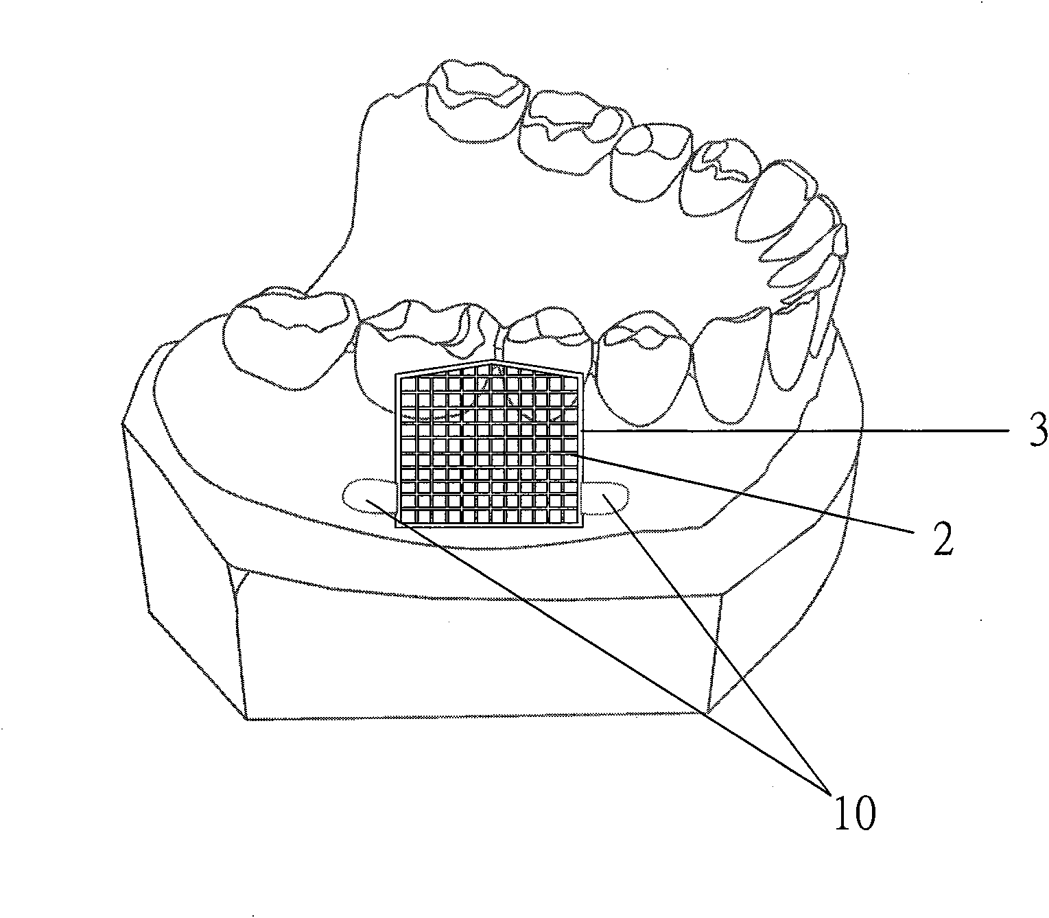
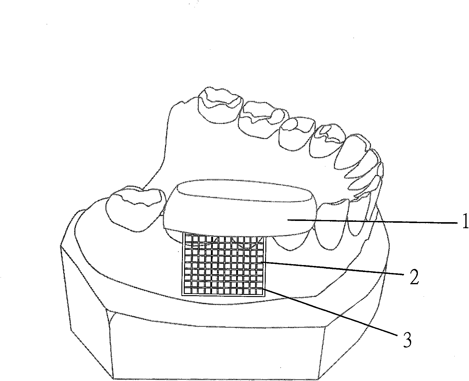
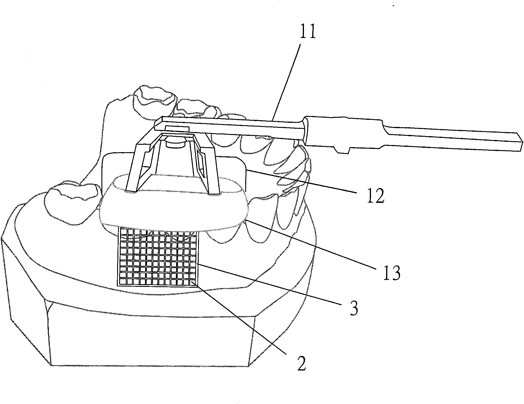
[0060] 1. Indirect method: Firstly, on the patient's working plaster model, determine the location where the orthodontic micro-implant is to be implanted, and the diameter of the micro-implant. Here is an example of implanting a micro-implant with a diameter of 1.2mm in the lower right of the patient. Between the first permanent molars and the second premolars, firstly select a three-dimensional network structure with an appropriate size and a basic measurement position, for example, the basic measurement unit is 0.7mm, and fine-tune the shape of this structure so that it can be closely attached to the The shape of the gums varies from person to person (such as figure 1 ) and then fixed on the gingiva of the plaster model with soft wax, the length of which should not irritate the oral mucosa and the mucous membrane of the floor of the mouth.

[0061] Find an x-ray film holder (x-ray Holder) that will be used for X-ray parallel irradiation in the future, and use a pencil to ma...


PUM


Abstract

The invention relates to an interdental space direct measurement and oral cavity orthodontics micro-implant positioning implantation method which utilizes any material with the impermeable characteristics to X lines to make a three-dimensional netted structure with basic measurement units, the three-dimensional netted structure is directly attached to an oral orthodontics disease position or a gum positioned at the cheek side or the tongue side of a work model which is to implant an orthodontics micro-implant, and the three-dimensional netted works is also fixed on a tooth occlusion surface by utilizing silastic moulage materials with additivity property; before the materials with the impermeable characteristics to the X lines are not hardened, and an X line sheet holder is firstly prepared to irradiate parallel to the X lines to leave marks on the silastic moulage materials with additivity property so that the check of the X lines is not easy to change positions for the time to come; after the materials with the impermeable characteristics to the X lines are hardened, the three-dimensional netted structure can be taken out from the work model and then placed into an oral cavity of a patient, how many spaces between two interdental spaces can be directly known on an X line sheet by the irradiation check of the X lines, i.e. the position to which the micro-implant is implanted can be immediately determined, and once the position is determined, a sleeve barrel with the dimension equal to that of the basic measurement units or integral multiple of that of the basic measurement units is arranged on the three-dimensional netted structure to lead the micro-implant or a drill to correctly enter the interdental spaces along the sleeve barrel in a right-angled direction.

Description

technical field [0001] The invention technology is about how to directly see the interdental space between two teeth in the patient's oral cavity and under the comparison of X-ray films in the department of orthodontics, and immediately determine the micro-implant desire. Once the implantation position is determined, under the guidance of the guide sleeve, the direction of the micro-implant entering the bone can be correctly reached at a right angle to the desired position. It will not damage the root of the tooth due to the difference in the patient's lying position or the doctor's operating position. Background technique [0002] Orthodontic micro-implants have been widely used in the past few years. One of the biggest failure reasons is the damage to the adjacent tooth root. This is because the traditional positioning method is a rough estimate, and the X-ray parallel irradiation method is wrong. Traditionally The orthodontist uses 0.4~~0.5mm brass wire to bind the inter...

Claims


Application Information

Patent Timeline
IPC IPC(8): A61B6/14A61C8/00
CPCA61C8/0096A61C1/084A61C8/0089
Inventor 姚英超
Owner 姚英超
Learn More