Unloading off-circuit tapping switch

A tap changer and unloading technology, applied in the direction of transformer/inductor coil/winding/connection, transformer, electrical components, etc., can solve the problem of cage switch insulator rigidity improvement and limited protection, switch volume transformer volume increase, transformer Increased effective space and other issues to achieve the effect of enhancing work reliability, reducing switch volume and improving insulation level

Inactive Publication Date: 2009-11-04
WUHAN TAIPU TRANSFORMER CHANGER
View PDF1 Cites 10 Cited by
  • Summary
  • Abstract
  • Description
  • Claims
  • Application Information

AI Technical Summary

Problems solved by technology

[0002] In the Chinese patent CN201167022Y, a non-excitation cage tap changer cage strip unloading structure is disclosed, which is characterized in that a reinforced cage is added outside the original cage switch, and the transition between the two cage strips is through a soft connection. The tensile stress is eliminated, which protects the contact part of the switch contact. However, for large-scale tap changers, especially for high-current and high-voltage switches, the tensile force on the outer cage strip is still very large, so The unloading structure is still very limited in improving the rigidity and protecting the cage switch insulator
At the same time, the field strength of the high-voltage switch is relatively large, and there are many charged bodies in the cage structure. The use of this unloading structure increases the effective space of the transformer occupied by the switch. Huge volume, more complex structure, higher cost, and the increase in switch volume also leads to an increase in transformer volume
Moreover, the terminals on the reinforced cage outside the tap changer are distributed on the same level, which will also reduce the insulation performance of the switch to a certain extent.

Method used


Image

  • Unloading off-circuit tapping switch
  • Unloading off-circuit tapping switch
  • Unloading off-circuit tapping switch

Examples


Embodiment Construction

[0013] An embodiment of the present invention will be described below in conjunction with the accompanying drawings.

[0014] An embodiment of the present invention will be further described below in conjunction with the accompanying drawings.

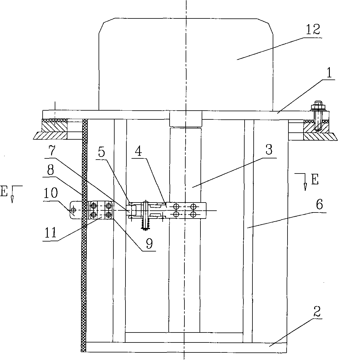
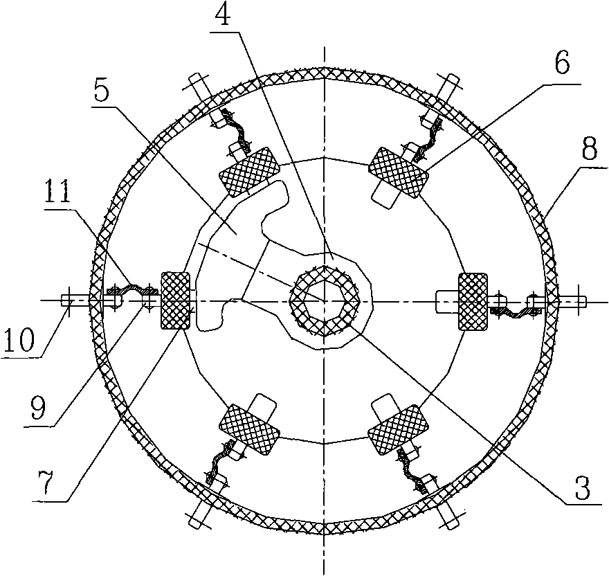
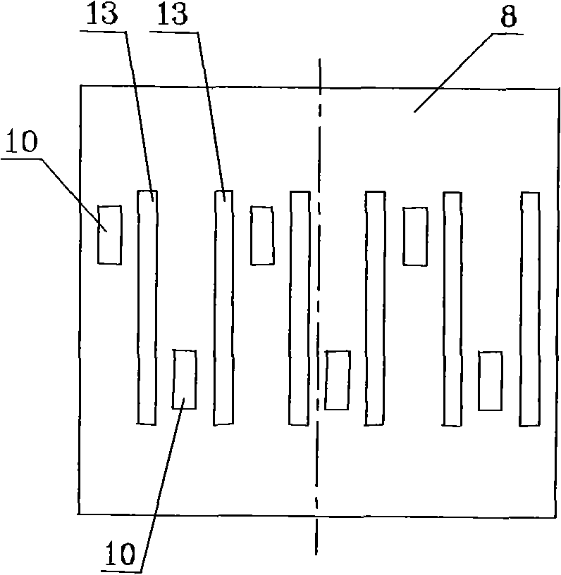
[0015] Examples of the present invention are figure 1 , 2 , 3, it is a single-phase five-speed non-excitation tap changer, including an upper support 1, a lower support 2, and a rotating shaft 3 is installed in the upper and lower support, and the rotating shaft 3 is connected to the operating mechanism 12. On the rotating shaft A support 4 and a moving contact assembly 5 are installed, and an insulator 6 is connected between the upper and lower supports. The insulator is a cage-shaped insulator, which is composed of 6 insulating rods arranged at intervals in the circumferential direction; the inner side of the insulator is installed The first layer has a static contact 7 corresponding to the moving contact assembly, the rear end of ...


PUM


Abstract

The invention relates to an unloading off-circuit tapping switch used in a transformer, comprising an upper pedestal, a lower pedestal and a rotary shaft which penetrates through the upper and lower pedestals, the rotary shaft is provided with a support piece and a moving contact assembly, an insulator is linked between the upper pedestal and the lower pedestal, a fixed contact configured corresponding to the moving contact assembly is mounted at the inner side of the insulator, the difference lies in the fact that an outer insulating cylinder is mounted on the periphery of the insulator, theouter insulating cylinder is provided with spaced connecting terminals, an inner end of the connecting terminal is linked with a leading-out terminal on the insulator via a linkage conductor, the leading-out terminal is connected with the fixed contact, and two adjacent connecting terminals are distributed in an axially and vertically staggered manner. The invention dramatically ameliorates electric field distribution of the switch at the same time of unloading, and the adjacent connecting terminals are distributed on the outer insulating cylinder in an axially and vertically staggered manner,thus further improving insulating level of the adjacent terminals; the invention is simple and compact in structure as well convenient for manufacturing and installation, The invention is suitable for tapping switches of high voltage and large current in particular.

Description

technical field [0001] The invention relates to an off-excitation tap changer used in a transformer, in particular to an unloading off-excitation tap changer and its connection terminal structure. Background technique [0002] In the Chinese patent CN201167022Y, a non-excitation cage tap changer cage strip unloading structure is disclosed, which is characterized in that a reinforced cage is added outside the original cage switch, and the transition between the two cage strips is through a soft connection. The tensile stress is eliminated, which protects the contact part of the switch contact. However, for large tap changers, especially for high current and high voltage switches, the tensile force on the outer cage strip is still very large, so The unloading structure is still very limited in improving the rigidity and protecting the insulator of the cage switch. At the same time, the field strength of the high-voltage switch is relatively large, and there are many charged b...

Claims


Application Information

Patent Timeline
Patent Type & Authority Applications(China)
IPC IPC(8): H01F29/04H01F27/32H01H1/56
Inventor 刘刚
Owner WUHAN TAIPU TRANSFORMER CHANGER
Why Eureka
Try Eureka